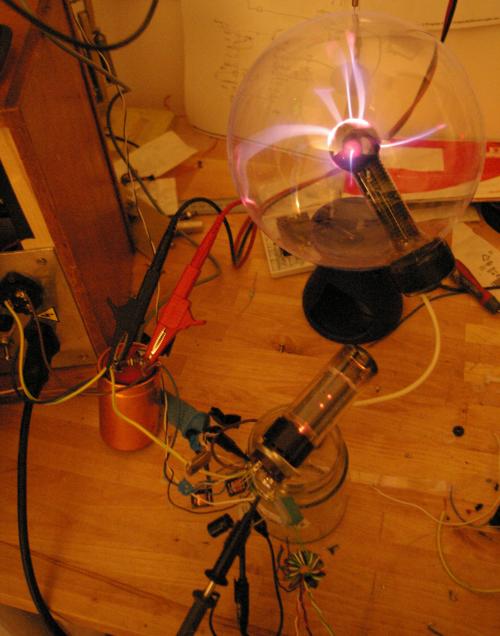
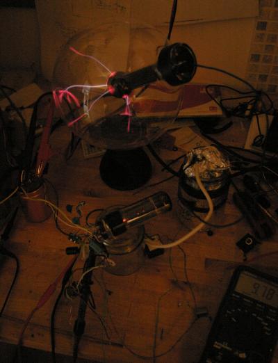
Vacuum tube plasma globe conversion
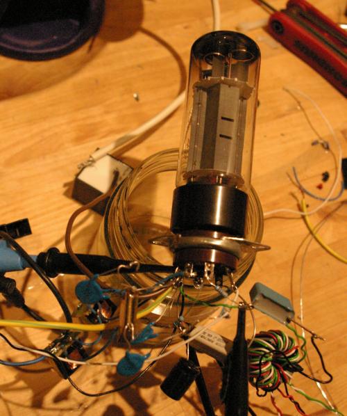
For the valve I tried an EL34 which is a popular audio power tube. In the end I also got it to work with a 6L6GC and a 5881 (both Russian clones.) A 6V6 that I tried would not work.
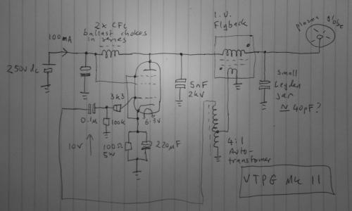
For the DC supply choke I used two inductors salvaged from a 20 watt compact fluorescent lamp (with HF ballast). I tried other chokes but these worked best.
For the Pi-tank inductor I tried the HV winding on various flybacks. The best result was with a small cube shaped unit I got from Mark Hales.
For the loading capacitor (input side of the tank) I used several 10nF 1kV disc ceramics in series. Best result was with two in series.
For the output side (tuning) capacitor I originally thought stray capacitance would be enough, but it seemed to be wanting more, so I added a Leyden jar. (jam jar wrapped in tin foil with a ball of tin foil inside) I was then able to increase the input side capacitance too: the streamers got bigger and the tube looked happier. If a pentode tube like the EL34 sees too high a load impedance, the screen grid wires glow red hot and can melt. If you look carefully you can see the screen glowing and adjust until it stops.
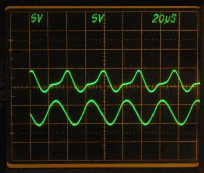
I drove it off a signal generator for tuning, but once it was performing well I wired it up to self-oscillate, taking feedback from the primary winding on the flyback. The voltage was not enough for reliable oscillation so I added a 1:4 autotransformer, made from a spare SSTC gate drive transformer. This gives enough drive to push the tube well into Class C.
The project was a success so time to build a nice base for it now.
P.S. The original MOSFET driver used about 15 watts. This one uses 25w (0.1A at 250V dc) to produce about the same looking streamers, excluding the heater which is another 9w on an EL34. It could probably be made more efficient but at the cost of more complexity.