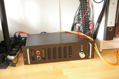
9 years old and still in daily use :)
In Winter 2007, I added a 4-star freezer badge, repainted the front black, and added a series capacitor to slow the AC fan down. I also finally tested the short circuit protection, since I was feeling bored and a little sadistic. It survived 10 shorts on each channel with a screwdriver while putting out full rated power into 4 ohms. Some of them made a pretty big spark, but every time, the protection circuit operated and turned the amp completely off.
Knowing what I know now, if the fancy Exicon MOSFETs had blown up during this test, I'd just have replaced them with ordinary transistors like the MJ15024 and MJ15025. Having said that, Exicon's eval boards never included any protection circuitry at all! Exicon MOSFETs are still available too.
9 years old and still in daily use :)
IMHO.
It took much tearing of the hair and gnashing of the teeth before I got the thing to work. At first it oscillated so badly that I thought I had picked up the plans for a radio transmitter by mistake. It turned out that I forgot the Zobel network. This item has a very scientific-sounding name but is really just a resistor and capacitor in series, connected between the speaker terminal and ground. Every power amp is supposed to have a Zobel network but it had been mysteriously left out of the circuit in the AD application note. Once I put it in, it worked perfectly.
I had to modify Mark Alexander's original design a bit, because I couldn't get the IGBT output transistors he used. I tried Exicon lateral MOSFETs instead, and they work a treat. To wring a little extra power out, I added extra regulated power rails (+/-66 volt) to run the driver circuit. The extra voltage means it can really thrash the MOSFETs.
I also redesigned the protection system to make it short-circuit proof. If the amp starts to clip or current limit, it very quickly mutes the audio, and if that didn't clear the fault, it turns itself off completely. In practice, the high speed muting circuit causes vile-sounding distortion, and the amp won't stand any significant degree of clipping without shutting down.
I guess I could modify it, but I think this just hammers home the point that this amp is not intended to be overdriven, and if it deviates from its piece-of-wire behaviour, it lets you know all about it.
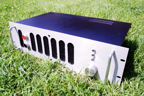
Outside view
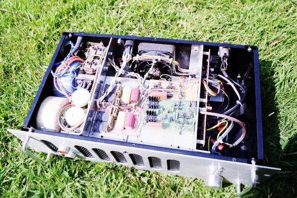
Innards. This amp has two totally separate power supplies. Each channel has its own 160VA toroidal transformer and 10,000uF filter caps, supplying +/-50 volts to the output stage. Only one output stage is visible: the other one is hanging underneath, and the two heatsinks fit together to form a letterbox-shaped cooling tunnel that accepts air from the front grill. With a dissipation of around 50W per channel at idle, it sure needs it :-/
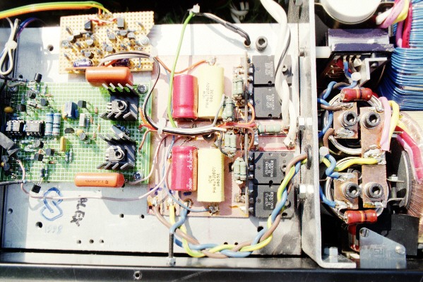
Close-up of the output stage. The two complementary pairs of Exicon MOSFETs were the most expensive and hardest to get parts of the project. There is about 250 USD worth of MOSFETs in the amp. Note the electrolytic (red) and polypropylene (yellow) caps that give extra decoupling for the +/-50V rails, and the low inductance wiring methods to try and avoid parasitics. I never found any need for an output choke, but maybe that was just because I never formally tested it with extreme capacitive loads.
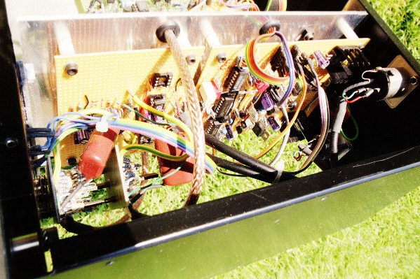
The preamp compartment. The volume control is actually a 21 position, 2-pole rotary switch with a resistor network. It gives 3dB per click and channel balance of 1%. I did it this way because I had one of those switches in my junk bin looking for an application. There's plenty of room left in there for something nice like a DAC, or maybe even a tube distortion simulator ;-)
Driver and output stage (Spot the "deliberate" mistake)
Protection 1: the Destructo circuit
I also read Douglas Self's Audio Power Amplifier Design book. Apparently I wasted my money on MOSFETs and current feedback. The book also includes a dual- slope protection system which works the same as the Destructo but uses half the components. Bummer!
In Winter 2002 I added a speaker relay because I finally got fed up with the massive turn-on/off thud that it produced. I had to add a couple of transistors to drive the relay. So I suppose this is Rev. B.
It's January 2005 now and the amp is still in daily use. It still hasn't been short-circuit tested.
You are allowed to build this amplifier only for your personal use. If you want to produce the amplifier commercially, you must take out a license from Analog Devices. I think.
The original Analog Devices application note is AN-211. You can find it on their website at
http://www.analog.com/
I used to link directly to it but they keep moving it! Their search function should find it.