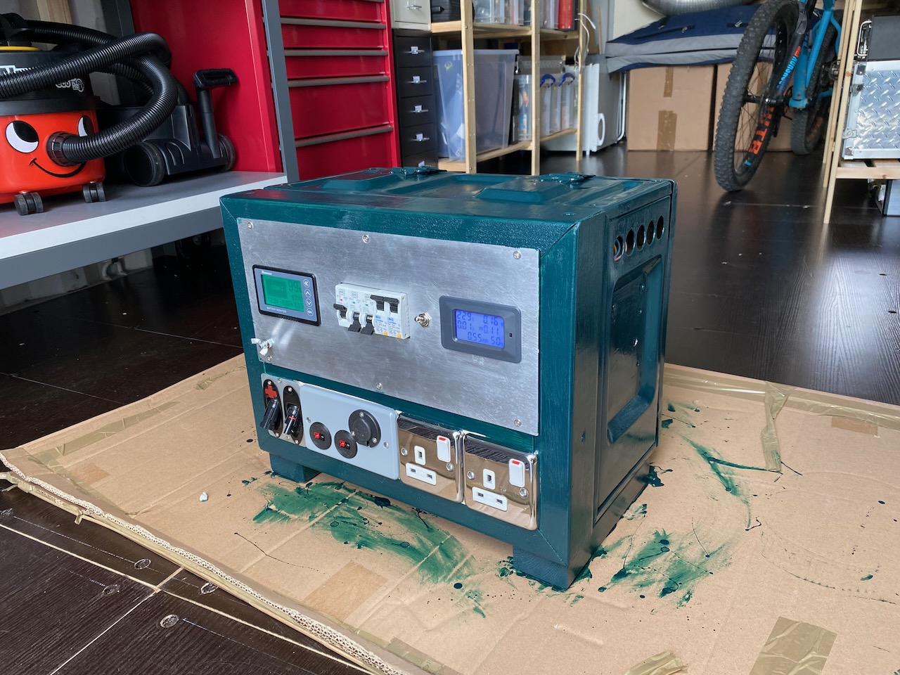
Fittingly the paint colour is Valspar “Thunderbolt” left over from painting the front door at home. Still waiting on some more industrial looking socket outlets to replace the chrome ones.
I’ve been warned that after going to Powerpole connectors for 12V DC distribution, I’ll never want to touch a cigarette lighter plug again. That sounds about right.
I am planning 3 weekend expeditions with the goal of ending up on Beinn Mheadhoin in the Cairngorms for my 141st Munro. The name means “Middle hill” and 141 is halfway round…
Expedition 1: Wild camping in the Alders *DONE* Munros 126-131 This expedition ended up done the other way around: setting off from Luiblea Saturday lunchtime, bag Geal Charn and Creag Pitridh, go via Bealach Leamhain and An Lairig to bivvy spot at Diollaid A’Chairn on Aonach Beag ridge, then following day bag ridge and return to Luiblea via track at Luibvan. Nav by map and compass in low cloud throughout
Day 1: Geal Charn, Creag Pitridh. Day 2: The Aonach Beag ridge: Carn Dearg, Geal-Charn, Aonach Beag, Beinn Eibhinn
Expedition 2: Up the Fannaichs *DONE* Munros 132-140 Thanks Allan Do 4 one day and 5 the other bringing the Munro count to 140- with support from a friend who did the same thing in February
Expedition 3: The Gorms *DONE* Munros 141 and 142 Bag Beinn Mheadhoin from Glenmore Lodge via Loch Avon, taking in Bynack More on way home.
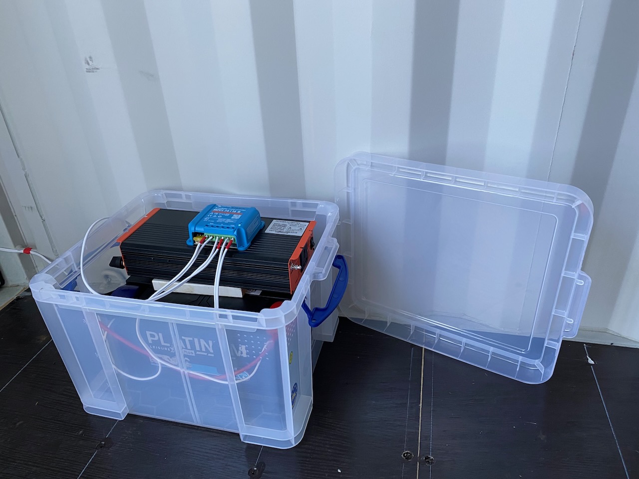
I’ve been renting a 20ft container to use as storage and workshop space, and wanted some electrical power.
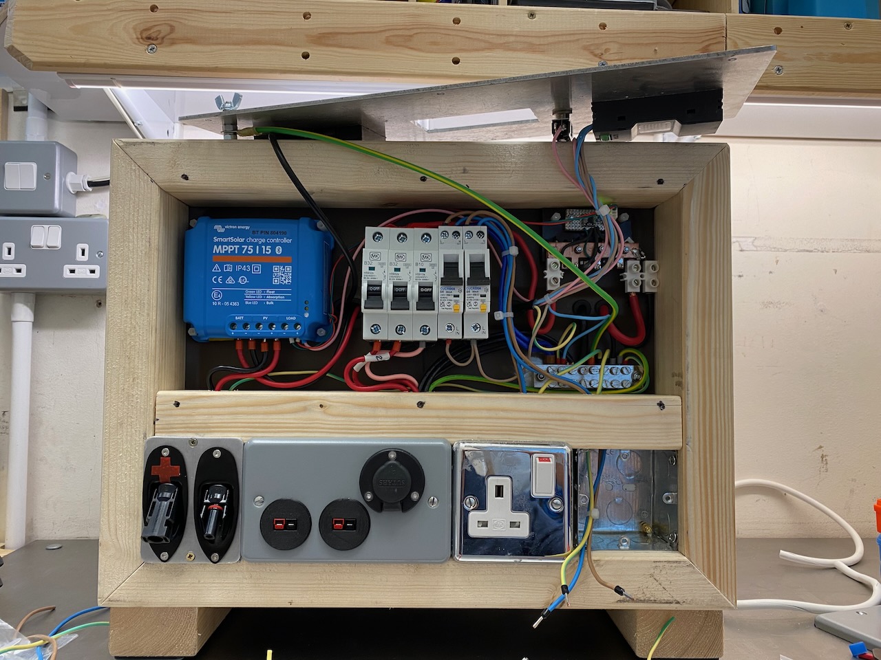
The prototype was not very elegant. 😀 The basic components are a 135W solar panel on the roof, a 12V 100Ah AGM leisure battery, a Victron MPPT charge controller, and a 1kW pure sine wave inverter.
The inverter is a reasonably priced “Mercury” branded unit from TLC Electrical. I believe the Chinese OEM is Ningbo Kosun. I may do a more detailed review in another post.
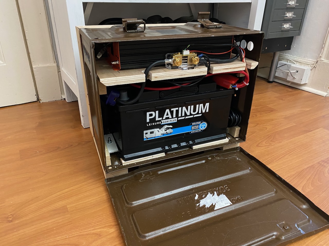
Lead-acid batteries aren’t great for geek points, but I thought it would be the best technology for the job. I only visit about once or twice per week and rarely drain the battery completely. It can also get very hot in there in summer, so the battery figure of merit I’m interested in is basically calendar life when fully charged at high temperature. Lead-acid offers a lot of that for the money.
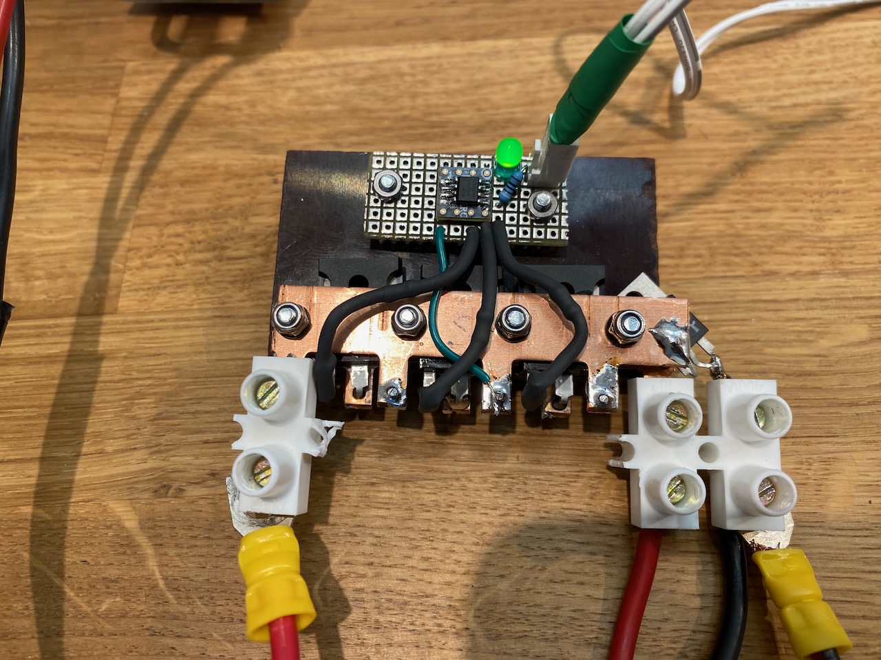
The first problem I found is that the Victron’s load output is wimpy. It won’t even run a 12V compressor. However the Victron has a good algorithm for turning off the load when the battery gets low to avoid damaging depth of discharge, and I wanted to make use of that.
So my first addition was a large MOSFET solid-state relay that would allow the Victron load output to control a much heavier load at 12V. I made this myself using 3x IRFP7430 MOSFETs in parallel, driven by a Si8712 isolated driver chip. The MOSFETs are rated at 40V, 195A, 1mOhm Rds(on). Turn-on and off seems to be rather slow. The small package on the right is a flyback diode to avoid a large transient when turning off an inductive load such as a motor. The MOSFETs would probably be ok with this, but it could damage other loads on the 12V bus.
The solid-state relay does not switch the supply to the inverter. This is connected directly to the battery to minimise voltage drop.
I modified the inverter to have a remote on/off switch, which was very easy as the internal on/off switch just connects 12V from the positive input terminal to the control circuitry. I simply hacked it so the control circuitry got its 12V feed from the Victron’s load output via a front panel toggle switch. This allows the Victron’s low battery algorithm to turn off the inverter alongside the other loads, and allows me to bury the inverter inside the enclosure with no access worries…
Note that I couldn’t find the official remote control panel for the “Mercury” inverter. I bought what I thought was the correct one on eBay, and on plugging it in, there was smoke… Luckily it all came from the remote and the inverter still appeared to be in good shape.
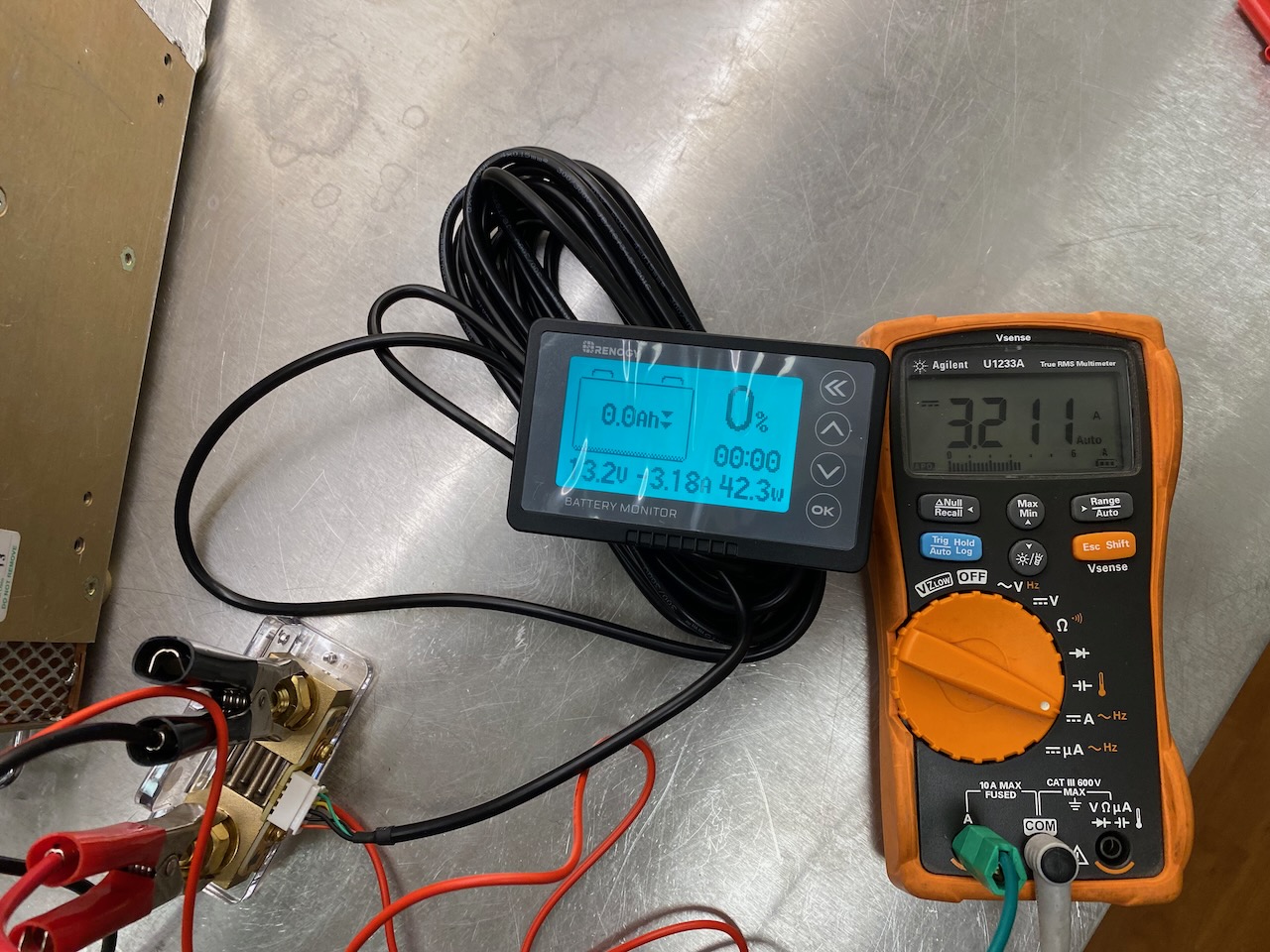
I also got this 500 amp battery monitor in Renogy’s Black Friday sale. 500A is overkill but it was cheaper than the lower current versions. The accuracy at low currents turned out to be fine.
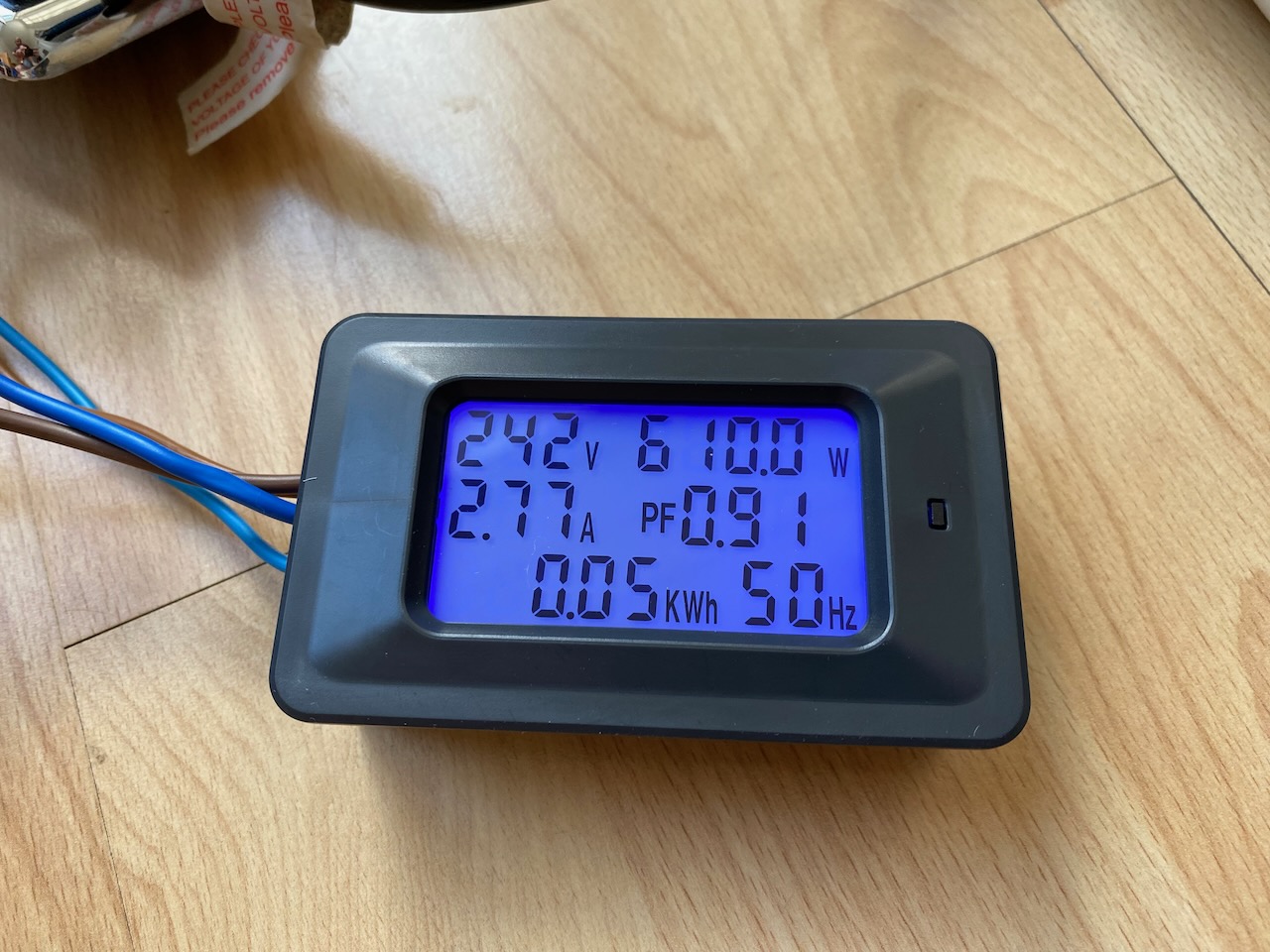
I wanted a visual indication that the inverter was on, and also some geeky statistics relating to the AC output. This power meter module from Amazon did the trick with its cheery blue backlight. It is powered from the AC supply, and this increases the 12V power draw of the inverter by about 1 watt.
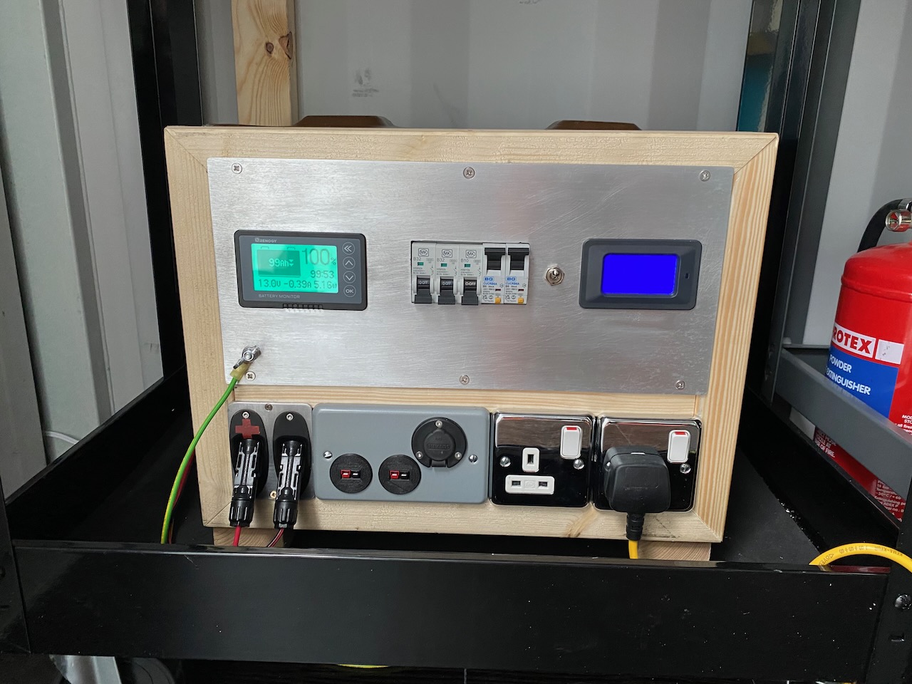
A British Army F632 ammo box was procured to fit all the parts in and… they didn’t fit. To gain some extra space, I added a wooden frame to the front made from CLS studs. I am quite proud of the Stratocaster jack cups as PV input connectors.
I provided 3 DC outputs: two Powerpole connectors protected by 32A circuit breakers and a cigarette lighter with a 10A breaker. Household AC circuit breakers do seem to work on 12V DC. I’ve seen them used up to 48V DC.
The inverter feeds two British standard socket outlets via RCBOs (earth leakage trips). In order for these to function the inverter’s neutral is connected to earth. Battery negative is also connected to earth and in use the earth stud is connected to the container. I believe this is the best overall solution from an electrical safety point of view.
The RCBOs do consume some AC power to perform their earth leakage monitoring function, but the amount is tiny, and doesn’t increase the inverter standby consumption noticeably. I tried Axiom and British General brands, and the BG ones had the lowest consumption.
These also have a 6A overcurrent trip function (the O in RCBO) but the inverter’s own current limiting would probably always operate before they tripped.
The inverter was mounted on a plywood divider and some holes punched in the sides of the box to promote airflow. I also removed the AC socket outlet from the inverter, leaving a large square hole for extra airflow, cut out the fan grill from the inverter casing, and reversed the fan. Hopefully these changes will make up for jamming it inside a relatively small compartment.
To be honest I have no idea if reversing the fan helped the inverter’s own cooling. Stock behaviour is to suck hot air out of the enclosure, and the old rule of thumb is that it’s always better to blow in cooling systems, but the inverter seemed like a quite well balanced and optimised design otherwise, so I can’t believe the designers left much on the table with sub-optimal cooling.
Really it was for my own convenience at a system level, the fan is at the 12V input end of the inverter and I wanted the hot air exhaust at the opposite end to the battery terminals, so I could have shortest possible battery wiring and a neat “signal path” from DC to AC without the inverter’s hot air blowing onto the Victron charge controller.
You might notice the lack of fuses on the battery positive terminal. Every connection to the battery is ultimately protected by a fuse or circuit breaker, but not directly at the terminal.
In use, you can see the inputs from the PV panel and the earth wire leading to an earth clamp on the container. (A steel framed building as far as BS7671 is concerned I guess.) The 12V and 240V wiring are not done yet.
The power bank itself could also do with a coat of paint and some more industrial looking unswitched AC outlets. The chrome ones are a bit flashy. Weighing in at 45kg (perhaps Power Tank would be a more appropriate name?) it also needs some serious handles to assist in moving it around…
I love the way the meter backlights come on when the inverter switch is flipped.
Appliances the inverter has run successfully:
Toaster, obviously
1kW electric heater
400W “Eco Henry” vacuum cleaner
Clarke CDP102 pillar drill
Clarke 6″ bench grinder
1200W travel hair dryer (output sags to 220V, hair dryer only produces 1kW)
Ikea TILLREDA induction hotplate (only up to 40% power…)
A selection of guitar amps (works surprisingly well with no noise issues)
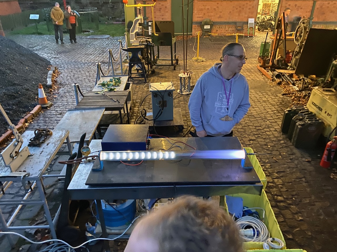
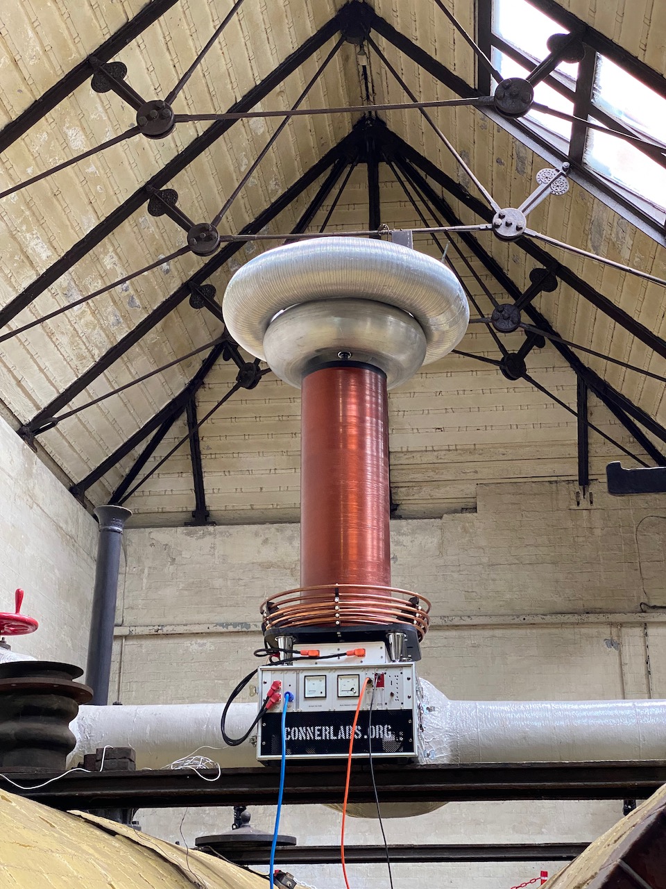
Odin made another appearance at Nottingham Gaussfest 2022. This year I got to run outdoors with a 32A 3 phase supply! A new spark record of 10ft was set, and a new power consumption record of around 15kW.
The Tesla Space Gun 2000 dub siren and drum machine were unleashed on an unsuspecting public.
I was so busy setting up and running the coil that I didn’t have a chance to get any photos.
For this year’s Gaussfest I decided to make a dub siren and connect it to Odin.
A dub siren is basically a very simple analog synth used to make sound effects for dub reggae. The original ones were a simple circuit with two 555 timers, but there are all sorts of variations on the theme. I was especially impressed by the Rigsmith GS1, which seems to contain some sort of toy sound effect IC.
I’m sure I had something similar mounted on the handlebars of my Raleigh Chopper in the 80s. How hard could it be to build one?
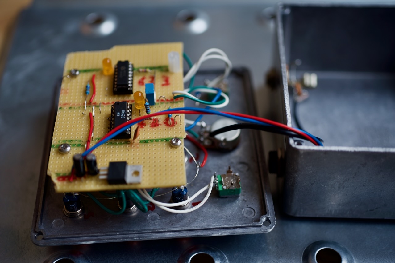
After some Googling and searching eBay, I found a surplus dealer selling some promising looking chips: the HK620 and HK623.
To make my dub siren I copied the data sheet application circuits almost exactly. The only change I made was to replace the timing resistor (“Rosc” in the datasheet) with a 1M pot in series with a 47k fixed resistor. I also added a 3.3 volt regulator so it could run off the standard 9V guitar pedal supply.
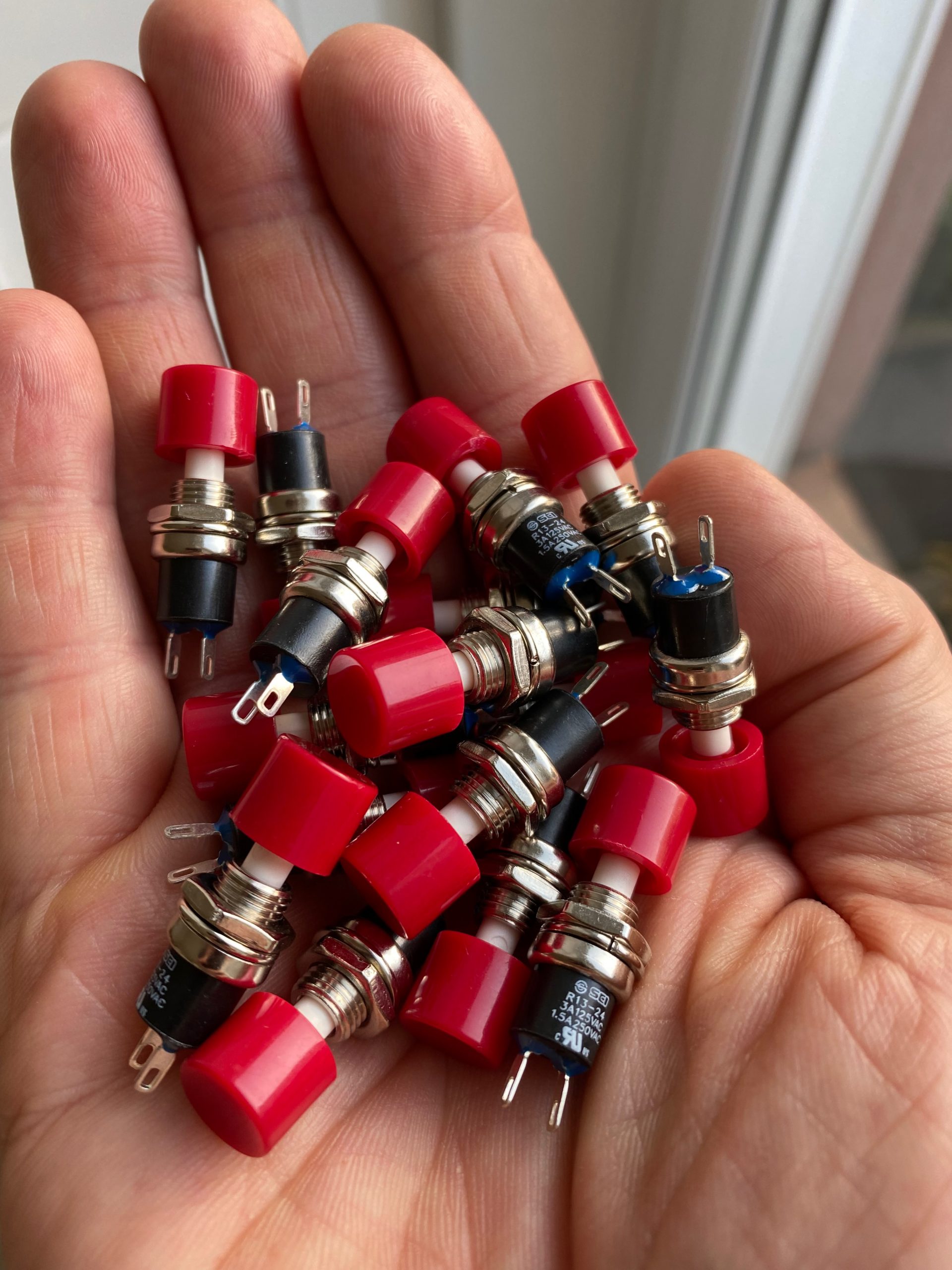
Buttons… So many buttons…And a Hammond diecast box and some other bits and pieces
It sounds identical to the Rigsmith! Have they been shopping at Budgetronics too? 😀
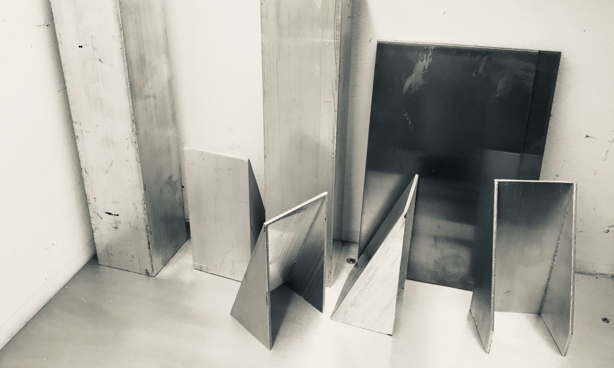
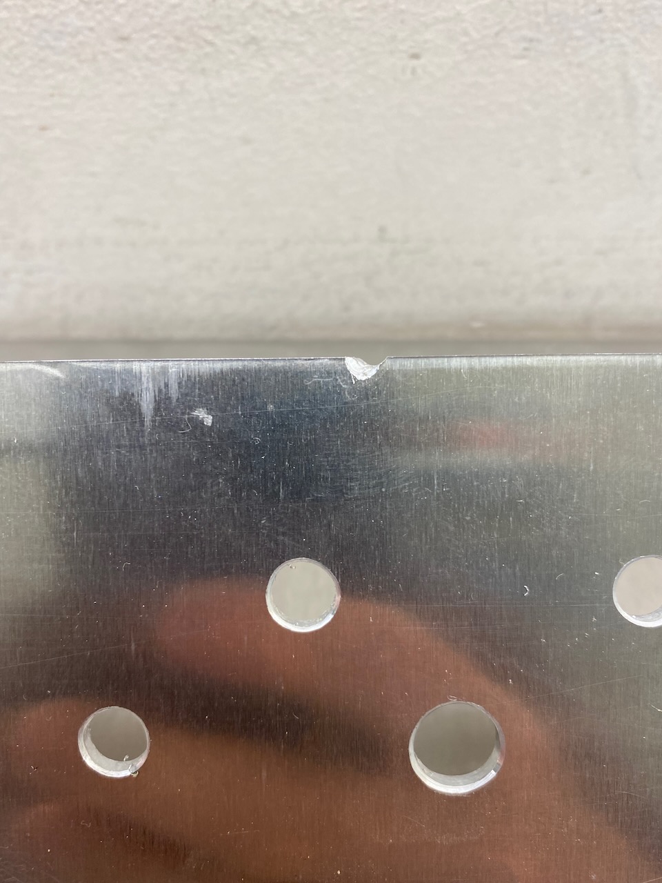
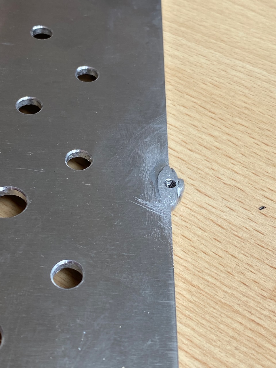
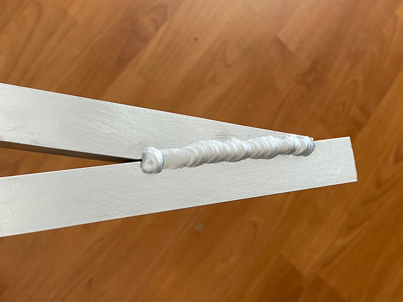
I started with a 3mm piece of aluminium pre-cut to size by Metal Supermarkets. The existing screw holes were easily replicated with PEM nuts, but the old faceplate vibrated horribly, so I wanted to add 2 more mounting bolts, and oh dear, the drilling for the top one just missed the panel.
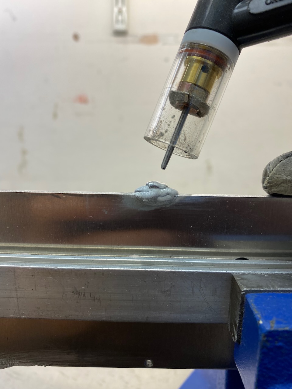
This was a perfect excuse to zap something with the TIG welder.
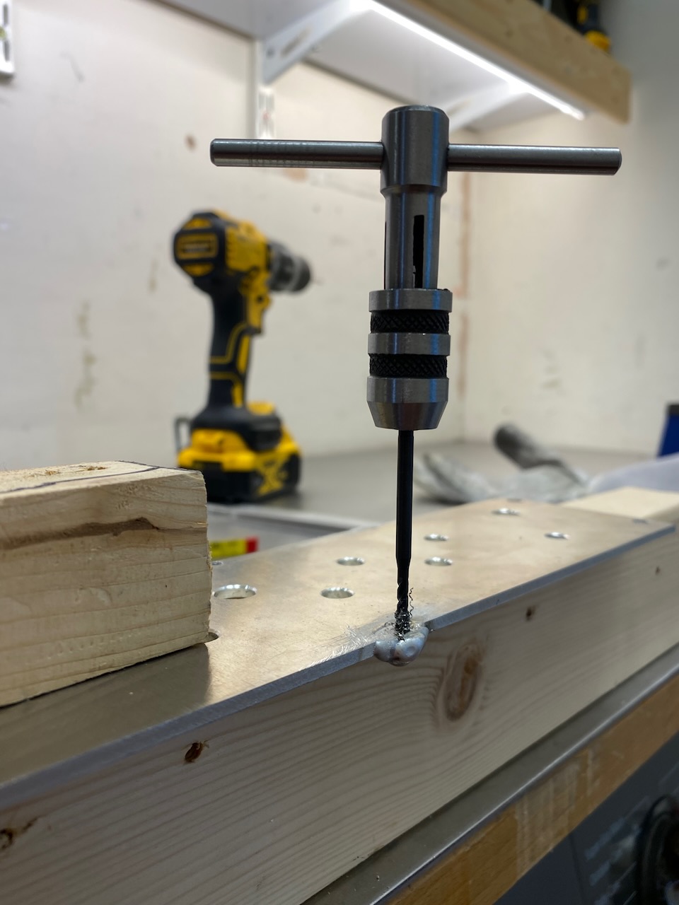
Zap and tap
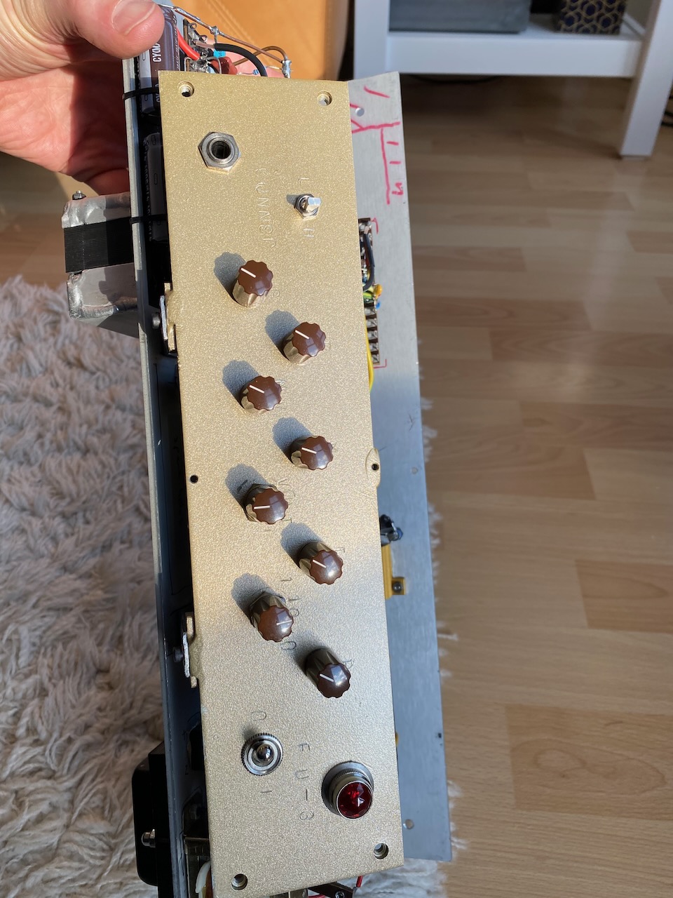
With this done, a coat of gold paint and a pasting with letter punches…
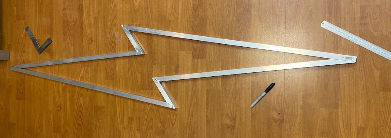
Wanted a track light fitting for the living room and more aluminium welding practice 🙂
20x20mm square tube (ashamed to admit I bought it from B&Q) was cut into the shape of a lightning bolt.
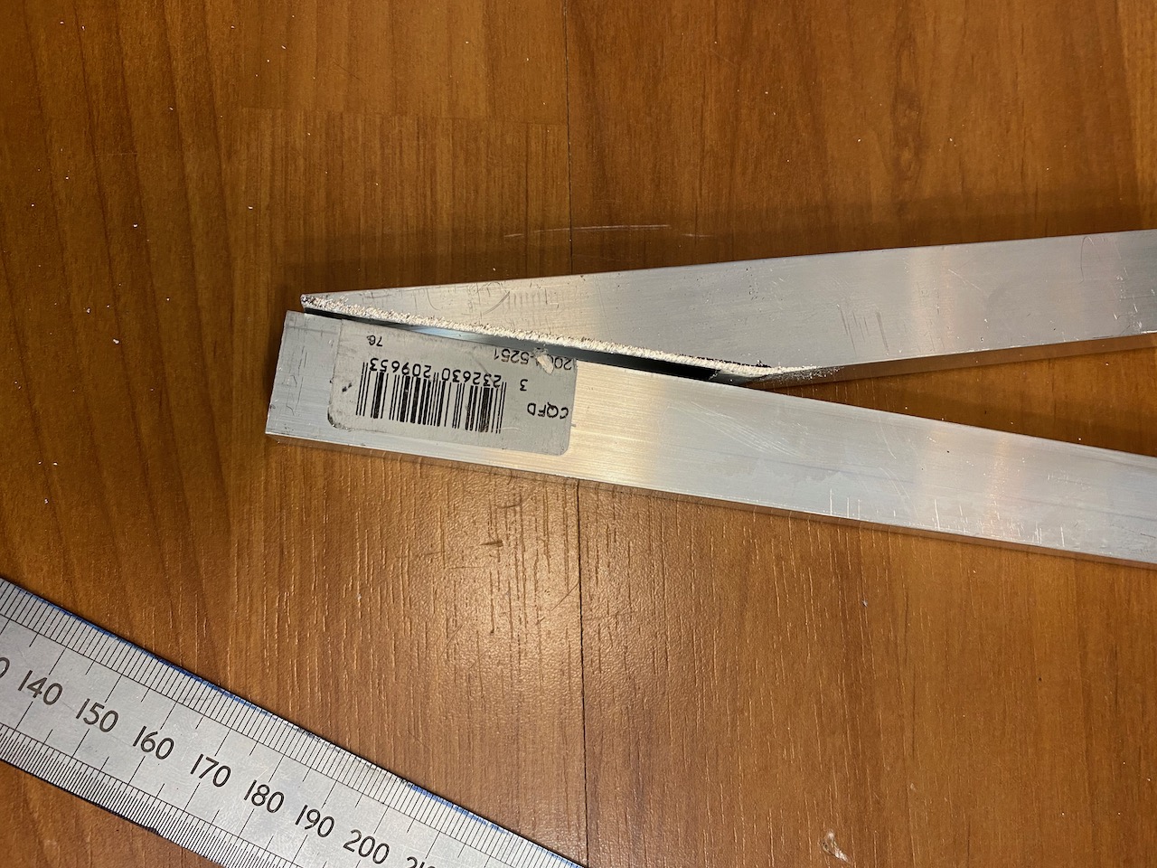
Oh dear, the mitreing could have been better…
This is the nicest weld, there were much worse 😀 I got off to a bad start by burning several holes in it while trying to tack it together, and had to weld up the holes. I didn’t realise the tubing was only 1.6mm thick and started off with too large a tungsten and too much current. Another reminder to always test the welder settings on a scrap of the material you’re going to use… 🙂
After fully welding (OK I didn’t do the inside corners 🙂 )
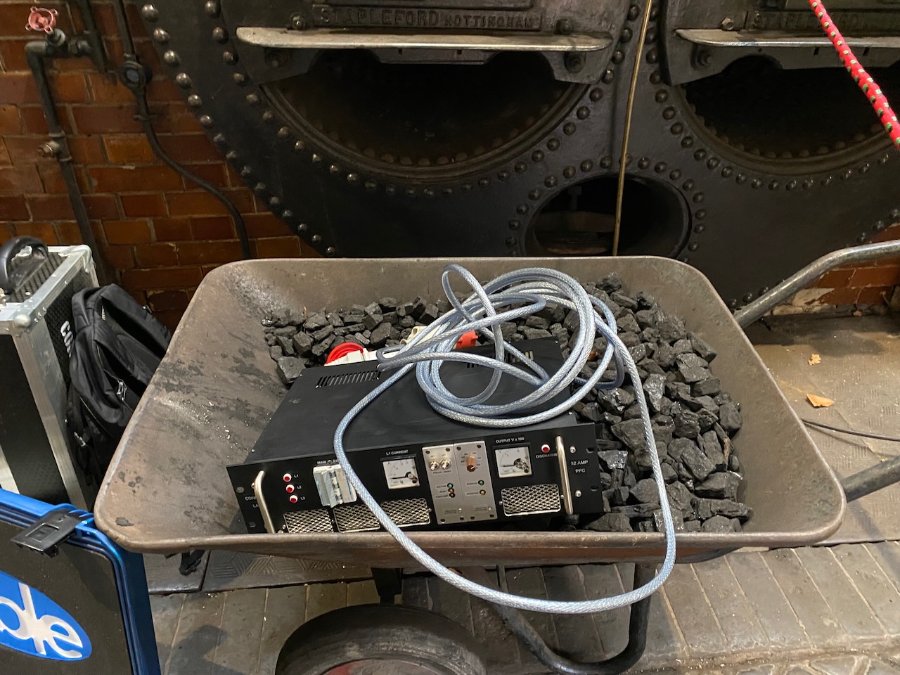
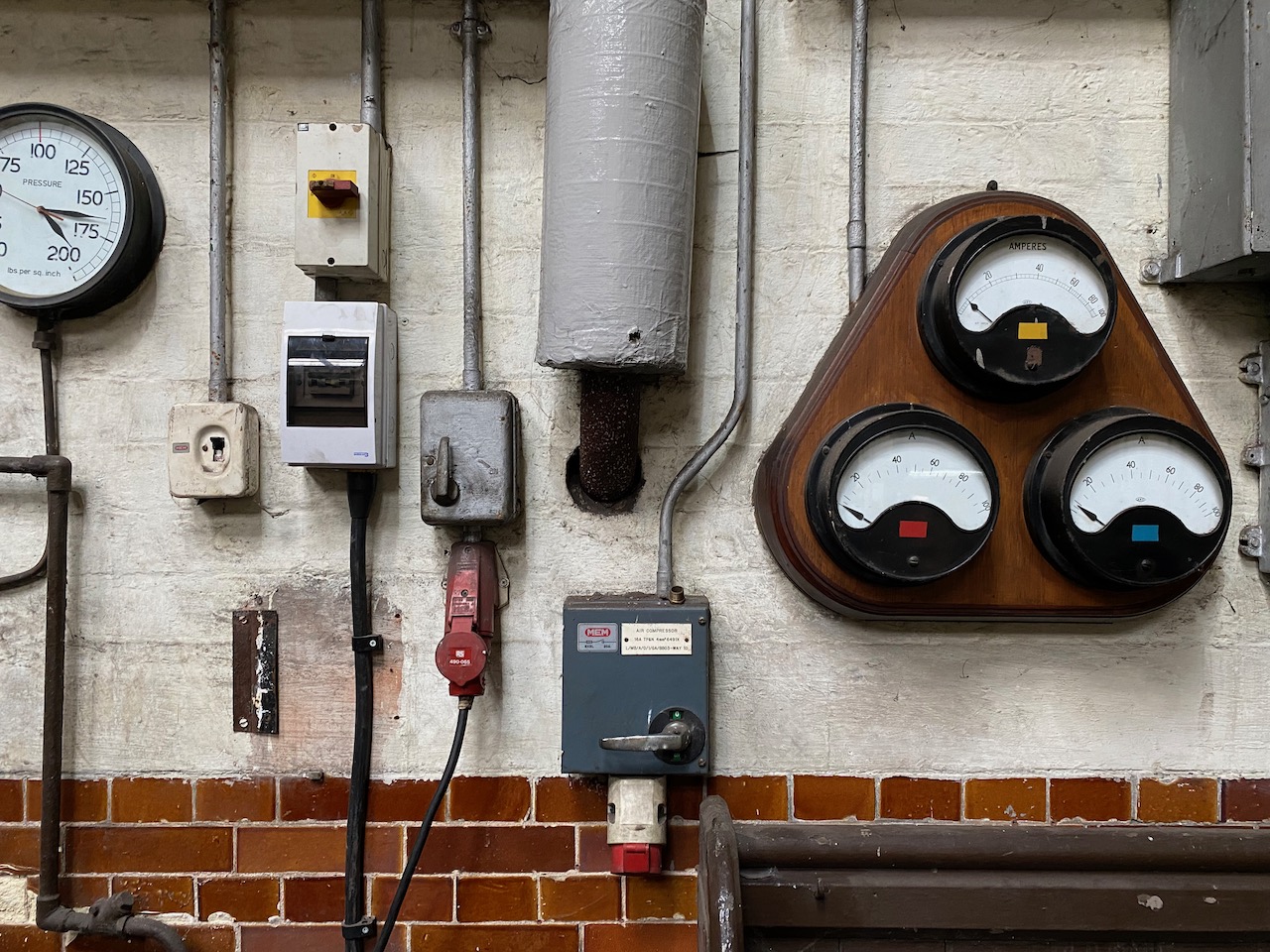
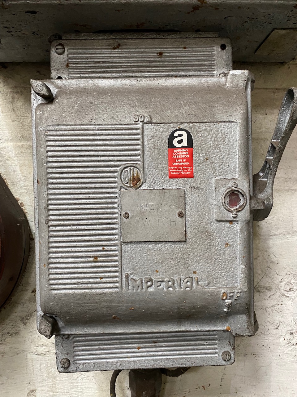
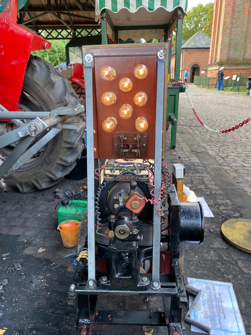
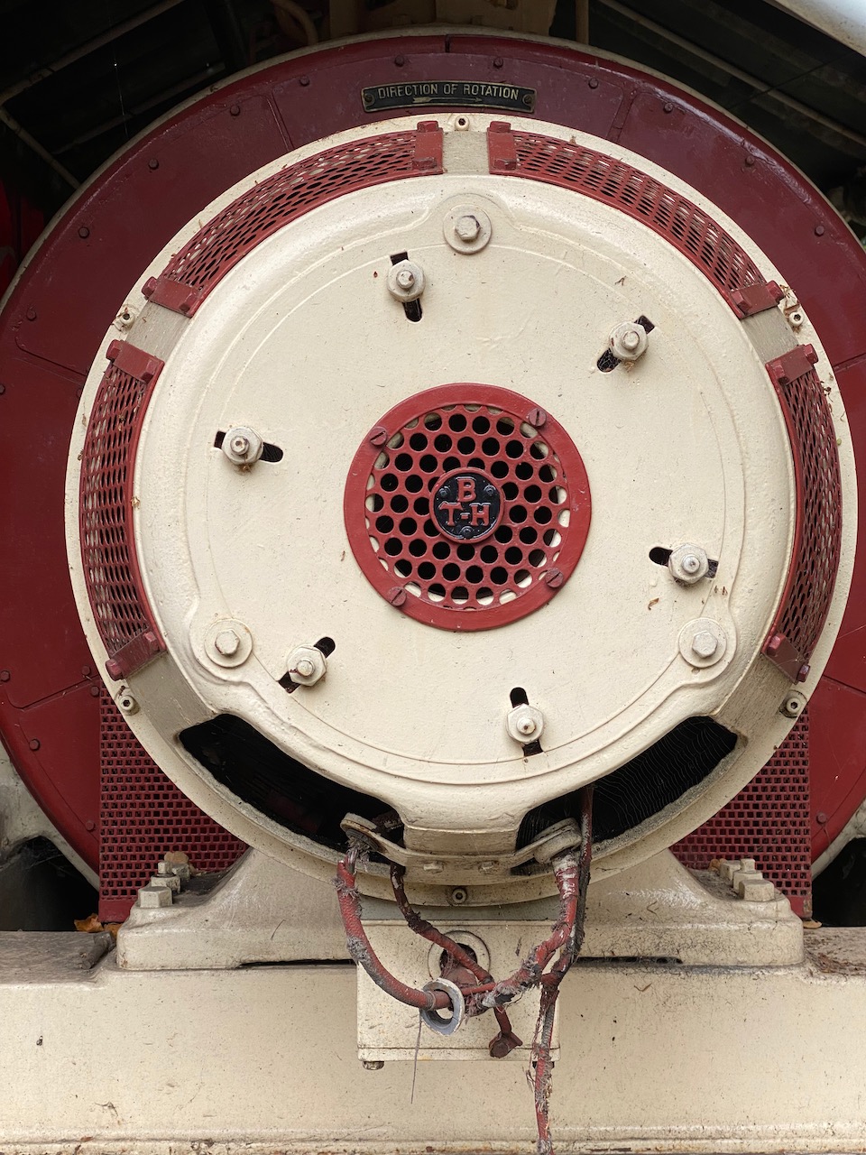
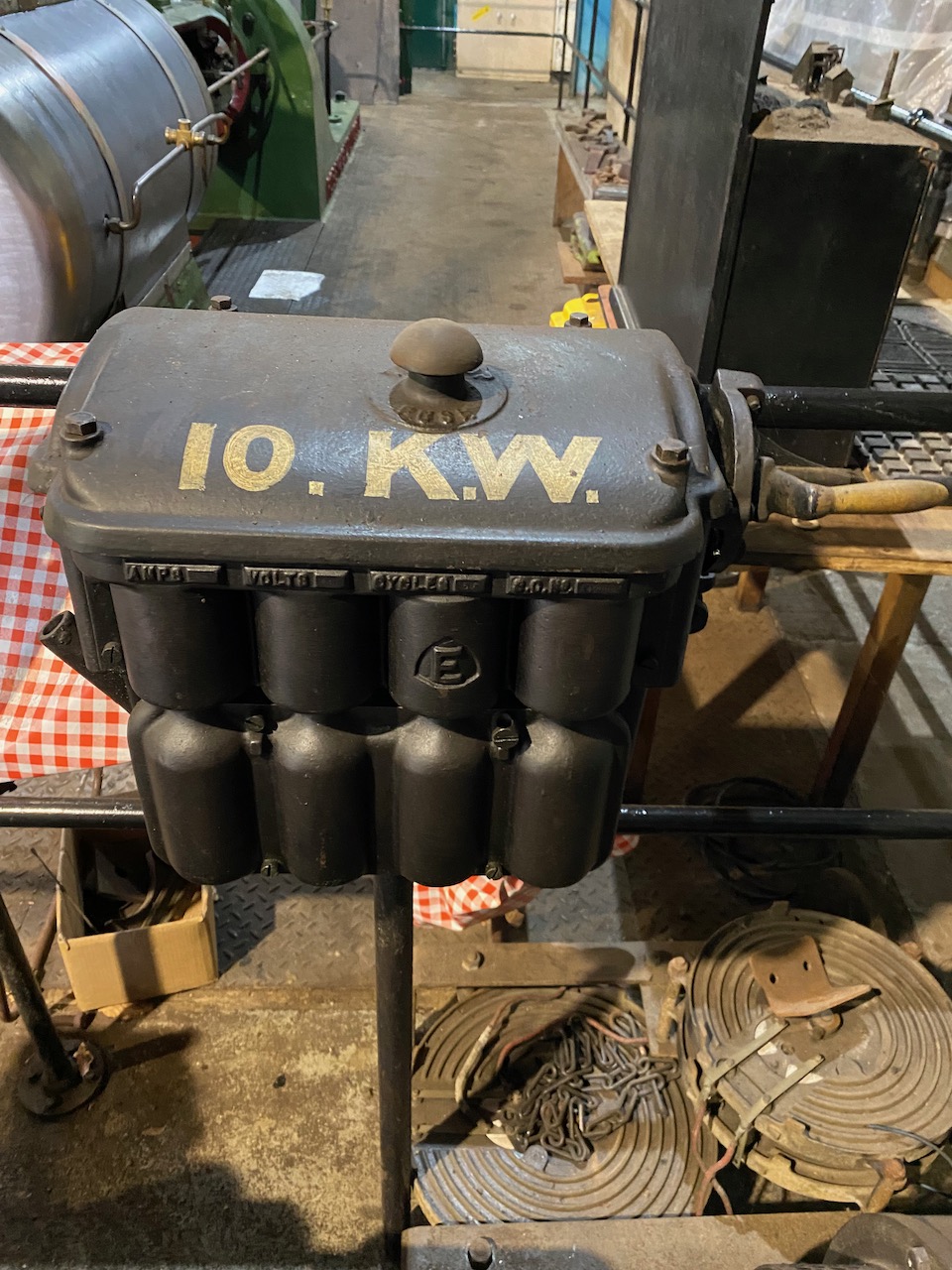
Boiler house switchboard… Yes my setup moved the meters 🙂 Mmmm, asbestosThis generator was a bit too small to power Odin 🙁This one was too bigMy performance did actually use about 10kWAn event like this would not be possible without defibrillators and a tea room.
As you can imagine from the number of acronyms in the title, this took a huge amount of fiddling and was very confusing, so documenting it here for my own benefit and others’. 🙂
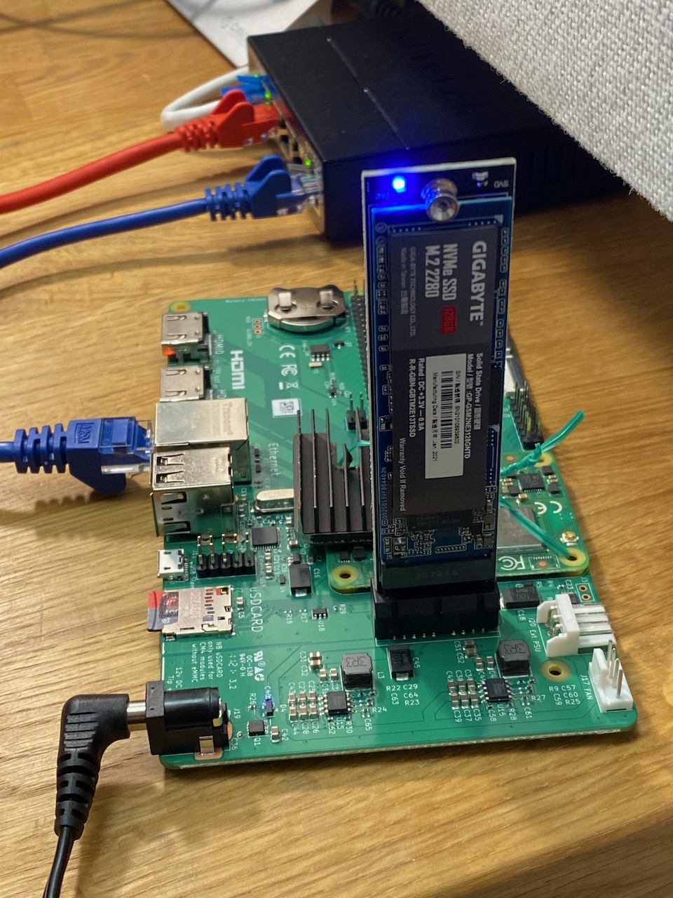
Those blue LEDs >_<
I wanted to run Ubuntu Server ARM64 on a Raspberry Pi CM4 dev board using a NVMe SSD for at least the root filesystem (and ideally booting from it)
Step 1: Update the CM4’s bootloader firmware
The CM4 probably has an older bootloader firmware installed from the factory that doesn’t support NVMe. This step is best done from a Linux PC: I used an old Acer laptop running Zorin 16. The below commands are to be entered in a terminal window:
First you need the latest version of the Raspberry Pi USB boot tool. This has to be built from source, and you may need to install some dependencies first (-1000 geek points if you didn’t already have git and build-essential 🙂 )
Now it’s time to build the USB boot tool from source…
git clone --depth=1 https://github.com/raspberrypi/usbboot
cd usbboot
make
Now you need to edit the boot order settings and get the latest EEPROM image. This part is adapted from this tutorial which doesn’t work verbatim any more (the “nvme” folder doesn’t exist in the usbboot repository, but substituting the “recovery” folder works)
cd recovery
sed -i -e '/^BOOT_ORDER=/ s/=.*$/=0xf25416/' boot.conf
NVMe on Raspberry Pi is still kind of bleeding edge, so it’s best to use the newest versions of everything. pieeprom-2021-07-06.bin was still the latest image at the time of writing:
Note: At this point the update script crashed complaining that it couldn’t find Python. I guess Zorin 16 removed Python 2.x and forgot to make Python 3 the default? The python-is-python3 package fixed that for me. Hopefully your Linux distro has a functioning “python” already, in which case don’t execute this command, it’ll probably break something!
sudo apt install python-is-python3
Finally it’s time to burn your changes to the CM4… The “disable eMMC Boot” jumper must be fitted on J2 for this to work (Unless you have a CM4 Lite I guess…)
cd ..
sudo ./rpiboot -d recovery
Now connect the CM4 Dev board J11 “USB Slave” to a USB port of your Linux PC and apply power to the 12V DC input.
The rpiboot tool should boot up the CM4 over USB and flash the new EEPROM image and boot order settings. Once the command line spew stops and the power LED on the dev board starts to blink rapidly, the process is complete and you can disconnect power.
Step 2: Try to boot from NVMe, fail
At this point I already had an ARM64 Ubuntu 20.04 LTS image downloaded from here and uncompressed to my Gigabyte GP-GSM2NE3128GNTD SSD. So I removed the SD card from my CM4 dev board and tried to boot from the NVMe.
I got a surprisingly informative error message from the Raspberry Pi bootloader (on a monitor connected to HDMI0)
start4.elf is not compatible. nvme boot requires newer software
So my first attempt at a fix was to update a 32-bit Raspbian SD card image with rpi-update and then copy the start4.elf and fixup4.dat files from that image to the NVMe boot partition. This got me to the next problem: The Ubuntu 20.04 image uses a version of U-Boot that doesn’t support NVMe, so it just sticks waiting for a boot device.
Next I tried downloading the Ubuntu Server 21.04 image and burning it to a SD card. I planned to go through the full process documented in the forum thread, starting with upgrading the Ubuntu image, so I inserted the SD card and powered up.
Step 3: Unexpected success
Imagine my surprise when it booted into Ubuntu 20.04 from the NVMe instead of 21.04 from the SD card as I was expecting. 😀
I guess what must have happened is that the boot partition on the 21.04 SD card had a version of UBoot that recognised the NVMe and treated it as a higher priority than the SD.
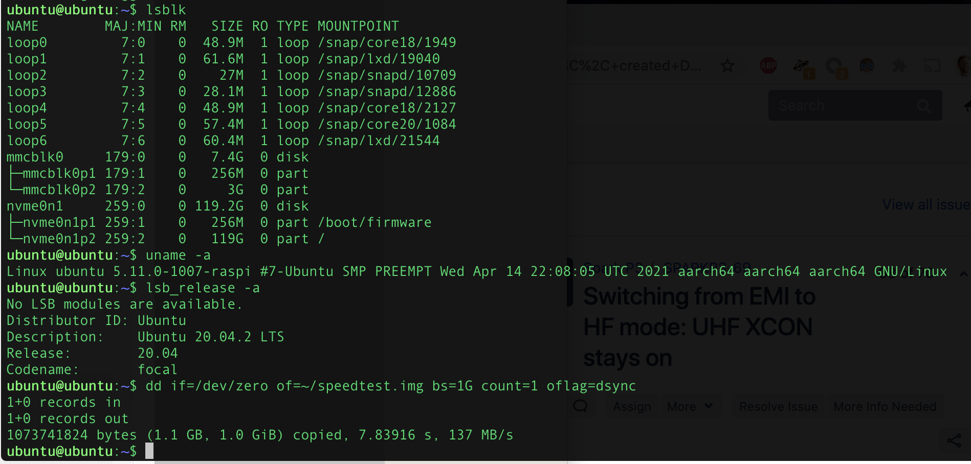
Confirming that the SD card is unused and root filesystem is on the NVMe SSD. It’s fast 8)
The next gambit would be to copy the boot partition from the SD card to the NVMe and see if it can boot directly from NVMe. But it works well enough as is, I don’t want to break it! This is left as an exercise for the reader 😉
Step 5: Try to make it boot directly from NVMe
Unfortunately on subsequent boots it flipflopped between NVMe and SD card as the root partition. So I thought since it’s Friday afternoon I should try to get it to boot directly from NVMe.
I started by deleting all files in the boot partition on the NVMe and replacing with the ones from the Ubuntu 21.04 SD card. The kernel is in /boot/vmlinuz, while the modules are stored on the root filesystem, so this would normally cause the modules to fail to load, except I noticed that I somehow managed to update the Ubuntu 20.04 installation on the NVMe so it was running the same kernel and modules as 21.04.
This still didn’t work, so I went back to that forum thread and replaced start4.elf and fixup4.dat with the ones from the updated Raspbian image.
Finally I got a direct boot from NVMe, with what I guess is Ubuntu 21.04 kernel and 20.04 userland. That works fine for me, I’d rather it ran a LTS version of Ubuntu.
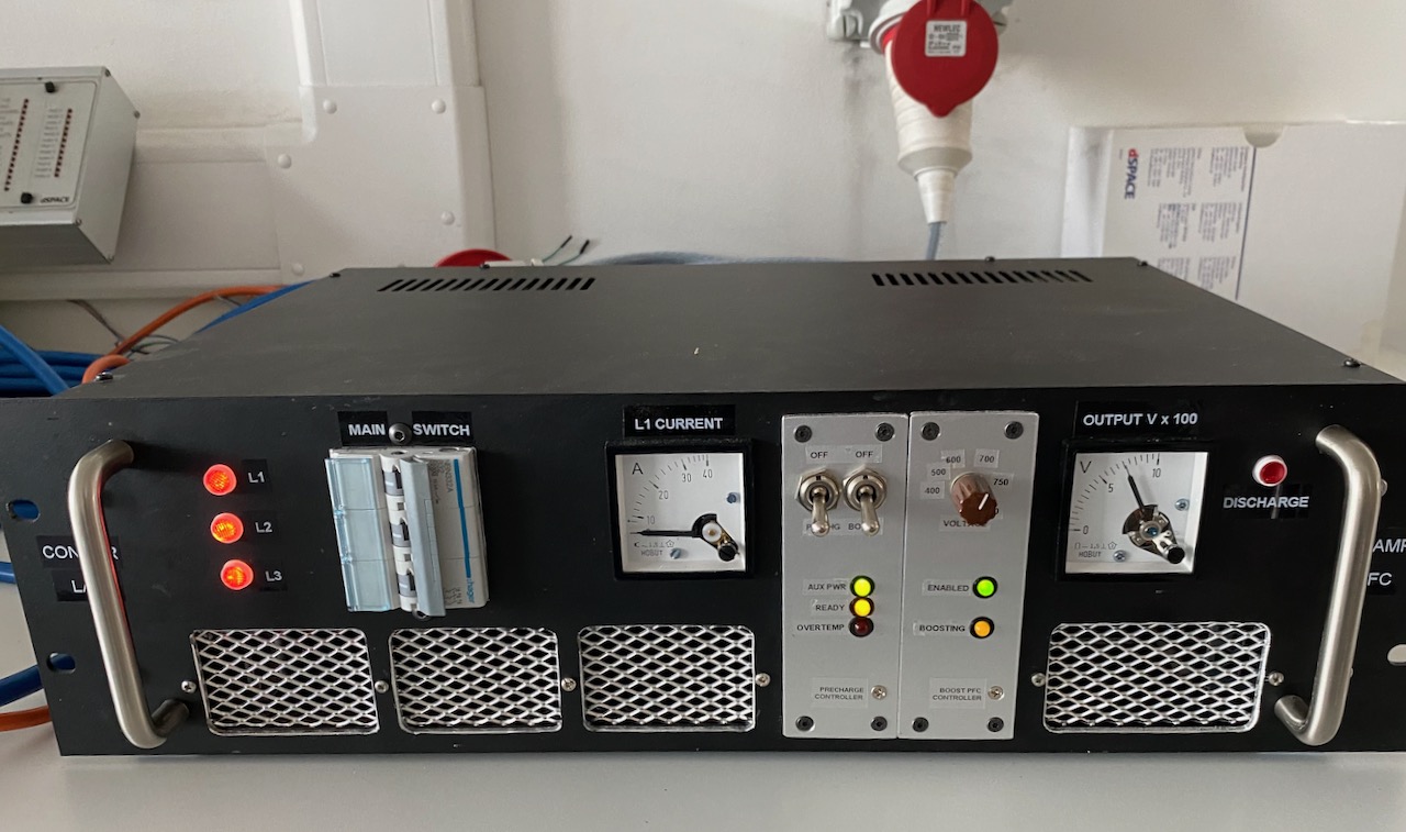
We plugged it into the 3 phase outlet and it started up normally! 😀
When smashed with 750V the Tesla cabin heater would draw an impressive amount of power while warming up. Unfortunately the steady state power draw was only about 2kW, probably something to do with the rather weak fan cooling it.
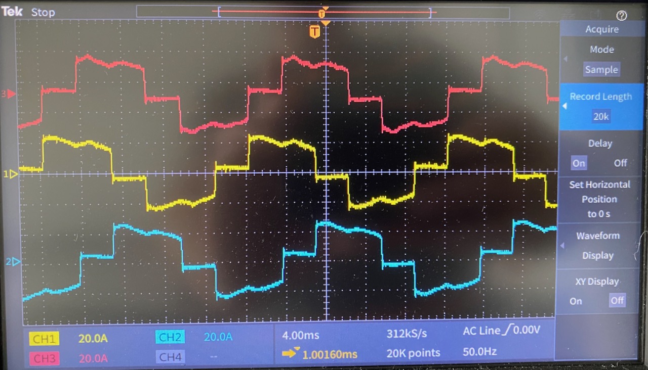
The PFC line current waveforms at (roughly) this 11kW output power level. No surprises here, they look exactly like the theoretical ones for this circuit. (Except strictly speaking the red one is upside down 🙂 ) The theoretical power factor for this waveform is 0.95.
We don’t have a 3 phase power analyser in the lab, so I used 2 single phase ones on the input, according to the old “2 wattmeter method“. To be honest this didn’t work very well, as the power drawn by the PTC heater was always changing, and it was impossible to make sure the 2 meter readings corresponded to exactly the same time. Also, the PF reading is rubbish due to the inherent 30 degree phase shift: to get the actual PF you have to plug the wattage readings into a complicated formula.
When the heater reached steady state, I measured an input power of 2000W, an output of 1900W, and a power factor of 0.96. From an academic point of view it would have been nice to measure the efficiency at higher powers, I expect that 100W is mostly switching losses and the efficiency will increase with heavier loads.
The main goal was to get confidence that the PFC would work at its first gig, and this has been achieved 🙂


