Cordell oscillator success

Well, the Cordell low distortion oscillator worked a treat! It didn’t work right away: I left a connection out of the PCB. And then I didn’t have a TL074 chip, so I tried a LMC660, and the chip blew up for some reason, which had me puzzled.

(I just checked the LMC660 datasheet: It’s specified for 15V total supply voltage. I fed it +/-16, a total of 32V. Whoops.)

Then, Cordell’s schematic calls for a 2N4091 JFET, a device with a high Idss and low on-resistance, but I couldn’t find any of those. I tried a BF245C, but it wasn’t strong enough. The AGC loop just whacked the gate as far positive as it could go, trying to turn the JFET “more than full on”. So I kept adding more of the things in parallel, until I saw the AGC go negative by a volt or two. I ended up with 5 of them, bodged onto a piece of stripboard.

A J111 would probably have been a better choice. These are the ones Douglas Self recommends as analog switches in “Self On Audio”, and they have a similar 30 ohm Rds(on). JFETs are so variable, though, you never know what you’ll get.

Frequency control with the “Blue Velvet” pot works great! There’s no noticeable amplitude bounce. Well, except for the fact that it’s backwards: anticlockwise to increase. I couldn’t see any easy way to dismantle the pot and reverse the action.

And, first time on the distortion analyser: 0.0015% at 1kHz! πŸ™‚ That’s better than the analyser’s own spec.

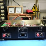
Stay tuned as we post some pics and stuff the thing into the spare bay of the DA4084.
A “Cordell” low distortion oscillator

Recently, I accidentally broke my low-distortion oscillator, the “Williams Memorial”. The breadboard was such a mess, that I decided it would be almost as easy to just build the Bob Cordell design.

I altered the design a bit: I replaced the switched attenuator for a plain volume pot, made the output balanced, and swapped the three LM318 op-amps for a single TL074.

I put a rectifier, smoothing capacitors and regulators on board. I’m hoping that my THD analyser mainframe will have a couple of spare transformer windings to power it, and the whole thing can fit in the empty left-hand bay where the SG505 would have gone, if I ever had managed to find one.

For the frequency control, I plan to try a 50k Alps “Blue Velvet” pot. I’m hoping the superior tracking and wiper resistance, combined with Cordell’s non-linear amplitude control scheme, and the integrating nature of the state-variable oscillator, will make it usable. I’m also hoping it can be taken apart and reassembled with the shaft coming out of the other end, to make it reverse log.

If that doesn’t work, I’ll use a binary set of switches, or something. That worked surprisingly well on the Williams Memorial. Eventually I’d like to try with 4066-type analog switches in current mode.

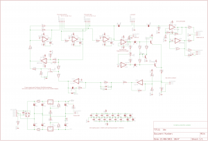
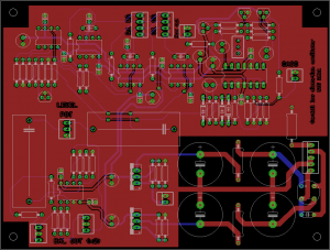
Anyway, here’s the schematic and a preview of the board.

Low distortion oscillator schematic

Image of low distortion oscillator PCB

Tektronix 7603 mainframe repair

Last week I was given a big heap of surplus test gear. It included a Tek 7603 oscilloscope mainframe. I already have a R7603, so it was nice to get another one, but sadly it was sick. On applying power, it just sat there, dead in the water, with wisps of smoke coming from the regulator board.

First of all I downloaded the service manual from bama.edebris.com.

Then I noticed half of the power rails were missing, as was the 130V rail fuse on the regulator board. Someone had obviously been at it before me. I replaced this fuse, and it blew immediately with a sizeable flash and pop.

It turned out that several transistors on the regulator board had failed, some short, some open. I replaced the TO92 ones with 2N5551 (NPN) and 2N5401 (PNP) and the larger metal can ones with 2N2219s, except for one that looked like it needed to stand a higher voltage, so I got a MJE340 and jammed it into the socket. The smoke had been coming from a crispy-looking 1.2k resistor which I replaced too, even though it still measured 1.19k.

After doing this, all rails were correct, and the unit powered up. However ALT mode wouldn’t work. I replaced a 7474 IC on the logic board (with a 74LS74 as I had no originals) and that fixed it.

Then, the readout wouldn’t work. On closer inspection, there was no readout board: I suppose it must have been optional.

The focus was still a bit blurry with the focus knob cranked all the way, but adjusting the focus preset in the HV box cured that.

Last of all, the graticule lights wouldn’t work. Usually it’s because all the bulbs are blown, but this time it was because the cable assembly that drives them was missing, presumed lost by the last guy who tried fixing it. I found a similar 4-pin cable in a box of junk, and the lights came on.

Finally, just when I thought I was done, I noticed the channels were bleeding into each other in Chop mode. I tried replacing the other 7474, but it made no difference. In fact there was nothing wrong with the beam switching, the problem was that the Y amplifier wasn’t settling properly after each switch. Now a scope Y amplifier is a major piece of analog voodoo: it contains dozens of tweaks to compensate its own frequency response, and that of the delay line. My refusal to settle had a time constant of about 50us, though, and the slowest trim listed in the service manual was 50ns, not a lot of use. However the schematic also showed two networks for compensating slower “thermals”, and it turned out that the trimpot in one of these had gone open circuit. I replaced this and since there was no trim procedure in the manual, I just tweaked both networks for minimum bleed between channels. I got it better than my other 7603.

I love how you can take a 40 year old piece of Tektronix gear, and you can find the schematics and fix it in a morning with parts that are lying around the place. They just don’t make ’em like that any more. Now it’s time to have a go at the HP 141T spectrum analyser. πŸ™‚

Blameless finished!

Here it is, pretty much done! The weather was pretty bad this weekend, so I spent most of it in the workshop, wiring everything up.

Besides the stuff I’ve already written about, there is a soft-start module (built rather messily on a tagboard), and a preamp/protection PCB. This contains Douglas Self’s anti-thump and DC offset protection circuit, a thermal cutout circuit using the spare diodes in the ThermalTrak power transistors for junction temperature sensing, and a balanced line input stage using the INA137 and NE5532.

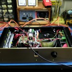
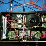
Here are some pics.

Gut Shot 1

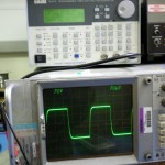
The 10kHz square wave response, just short of clipping, into a dummy load.

I’ll do some whole-system THD measurements some other time. (I broke the Williams Memorial Oscillator. πŸ™‚ )