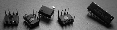
Note: If you watch Junkyard Wars, you probably realised that the programme makers don't leave it to chance. The junkyard is "seeded" with the required parts before every show. And so it was with the DWSSTC... I "seeded" my "junkyard" with the following:
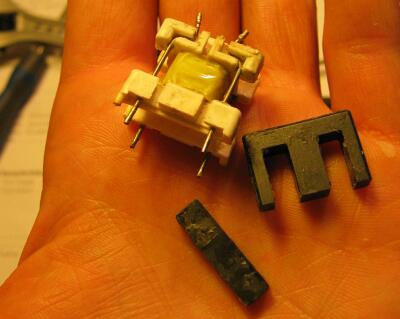
I started by looking for a core. Buying one felt like a cop-out: I was going to scavenge one. I started by raiding the bucket of dead switched-mode power supplies since they are full of ferrite cores. I ignored DC filter chokes (made of iron dust, yuk) and common-mode chokes (made of lossy ferrite- ugh) and finally in an old monitor PSU I found what I was looking for: A small transformer that coupled the driver chip to the base of the switching transistor... IOW, a base drive transformer... Almost the same thing!
I extracted the transformer from the board, placed it in an old cup, and poured boiling water over it. The glue softened and the core came apart easily.
Next, I made up the driver circuit I would be using in the finished SSTC, with UCC37321 and 37322 driver chips connected to an oscillator. This would let me test my new core by exciting it with a square wave. I also made a current transformer using a snap-on ferrite suppressor (from a microwave IIRC) with 9 turns on it and 4.5 ohm burden. I put a 16 turn test winding on the core and connected it to the UCC outputs via a 8 ohm resistor and the CT (wire passed through once)
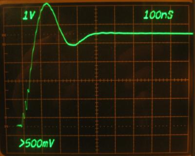
With the CT secondary connected to my scope, I could see the magnetizing current drawn by the test winding, and adjust the number of turns accordingly. Too few turns makes the current shoot up abruptly as the core saturates. (You can use this technique even if you don't have a scope- instead of a CT, put a flashlight bulb in series with the test winding and see how brightly it glows.)
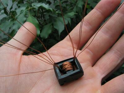
I settled on 12 turns as a reasonable number, and rewound the transformer with a 12-turn 5-filar winding. 5-filar= a rope of five pieces of wire twisted tightly together. I.e. one primary driven by the UCCs, and one secondary for each of my four MOSFETs. If you use this filar winding technique, you're almost guaranteed to get low enough leakage inductance. (see thedatastream's GDT design guide for more... and I mean MORE... details)
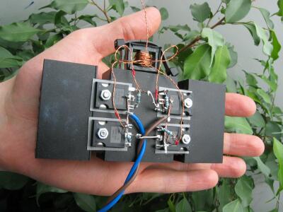
The bridge tested OK at 130 kHz with 300V DC input and no load (although one UCC did blow up) and also with 120V DC input and a 60 watt lightbulb for load.
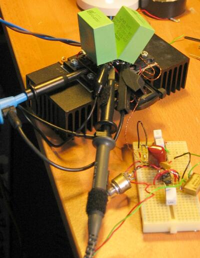
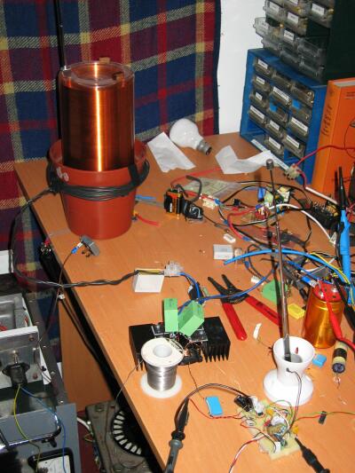
With the bridge working, it was time to hook it up to the resonator and let fly. But first
The primary coil was connected to the bridge output via a 2.2uF capacitor, and the bridge was driven by something similar to Steve Ward's Mini SSTC circuit.
Encouraged by this I tried it on 300V DC with an interrupter giving ~1ms bursts at 10pps. Budda Budda Budda BANG :( The UCCs were dead. I later figured out this was caused by my 12V power supply- the RF from the Tesla coil was sending it crazy and making it INCREASE its output voltage beyond what the UCCs could stand. But at the time, I thought it was a problem with the antenna feedback, so I changed to a fixed frequency oscillator.
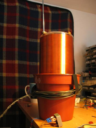
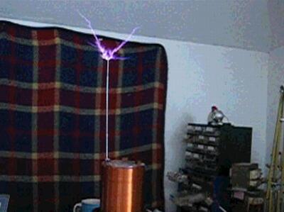
I replaced the UCCs and tried again this time with halfwave rectified 240V mains... BBRRRRMMMMM :) Result I could now claim to have a working SSTC!
However I wasn't very happy with the driver circuit so I decided to build a better one. That would be a job for next weekend...
But first a minute's silence for all the semiconductors who gave their lives to defend my freedom to build totally pointless things