
The power supply for this project turned out to be quite a challenge. I needed to deliver something like 4kW at 600V DC, from standard 230V mains, without using any transformers, otherwise it wouldn't be an OLTC. I also wanted it to be variable between 0 and 600V without using a variac, which after all is a kind of transformer. I checked out a variety of different designs, like a switched-mode system using IGBTs, but in the end I decided to use old-fashioned thyristors. I was attracted to thyristors because they are hard to blow up, easy to drive, and cheap. They also allow easy implementation of a soft-start, as opposed to a DC-DC converter running off a DC link with an uncontrolled rectifier, which needs some kind of resistor and relay arrangement.
If you have ever studied the operation of a lamp dimmer, you'll know what I'm talking about here. The principle of a thyristor controlled rectifier is exactly the same. However, the triggering circuit is a bit more complex. A light bulb is a nice resistive load and so a single pulse is guaranteed to fire the thyristor (or triac). A rectifier is a much more unpleasant load. If the firing pulse should come at a time when the AC line voltage is lower than the DC link voltage, none of the thyristors will fire. Later in the cycle, the line voltage might well rise high enough, but the thyristor won't "remember" that it got a firing pulse earlier, so it will never fire at all.
We deal with this by generating not just one pulse, but a rapid pulse train during the whole time that the thyristor is meant to be conducting. If the first pulse fails to fire it, one of the others will. This "hard firing" technique is common in industrial thyristor drives, but I have never seen a DIY circuit that does it, so I decided to design one.
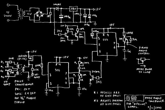
This circuit is based on a "soft start controller" circuit I found in the EDN Mag archives. It is in three parts- a power supply, an adjustable delay, and an oscillator to generate the firing pulses. The two trimmers marked (*) allow the length and rep rate of the firing pulses to be adjusted to suit your thyristors and pulse transformer. They should be long enough to fire the thyristors reliably, but not so long that they saturate the pulse transformer, and the rep rate should be low enough to let the pulse transformer core demagnetize between pulses. My setup worked well with 15uS pulses at a 4kHz rep rate.
The only drawback of this circuit is it fires both thyristors all the time. A thyristor with negative anode voltage won't fire, but the firing pulses supposedly cause it to leak more current than it should or something. You are really supposed to detect which thyristor has the positive voltage across it, and "steer" the pulses to that one only. Whatever! It seems to work fine.
This circuit isn't just good for controlled rectifiers. You can use it to fire a triac, alternistor, or pair of back-to-back thyristors for phase angle control of any AC load, even horrible ones like transformers and universal motors.
NOTE The component values above are for operating off a 50Hz line. For 60Hz, you need to change the 91k resistor for something a little smaller, or the circuit will behave strangely at minimum power; it'll suddenly start firing the thyristors at full power every _other_ half-cycle :-0
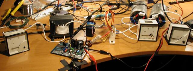
The system was hooked up for testing as above. Power came from the mains via a 0-240V 10A variac and moving iron ammeter (on left). Next was a line choke (the black transformer like object with white windings). The purpose of this is to broaden the current pulses drawn from the line, hence improving the power factor. I used 60 turns on a 150VA transformer core with a 1mm airgap, to give an inductance of veeerrryy roughly 1mH. The power then passes through a current transformer to the thyristor module (a Semikron SKKT-92 module containing two 92A 1600V thyristors). The thyristors are wired to the main filter caps (1200uF each) in the classic full-wave doubler arrangement, so the circuit should theoretically give up to twice the peak line voltage. Moving-coil meters show the DC output voltage and current. The DC output was loaded with a 1400W vacuum cleaner and 1200W hair dryer in series (both these appliances run happily off DC)
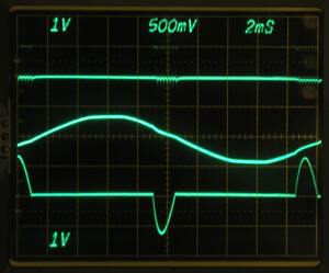
The above picture shows the circuit running at a large firing delay corresponding to about 200V output. You can see the multiple gate pulses, as well as the way that the line current pulses are broadened by the line choke. However you may note that the current pulses are delayed by at least 60 degrees relative to the voltage, hence the power factor will be awful. This isn't a problem: Because of the way the Tesla coil charging circuit works, it won't draw high current when the DC voltage is low, hence the AC line current should never be excessive.
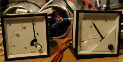
Here's what it does when the firing angle is dimed (UK: up to 11) allowing full power to flow. The output is 590V DC at 6 amps, that's a lot of power. Under these conditions the line current meter reads 18A RMS, hence the power factor is 0.8. That is not perfect but reasonable for a simple PSU made of stone-age components :) I also tried with the line choke removed, in which case the PF drops to 0.61, so the choke must be doing something.