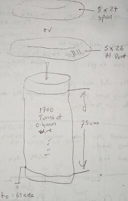
So how big should the secondary be? Well, there is plenty of evidence on the net that you can happily produce arcs twice or even three times the height of the secondary, without causing it to flash over and die. And, since we have a fairly low energy and high BPS, we can aim nearer three times than two. There is nothing worse than puny little sparks coming out of a huge coil. OK, now we have pinned down the secondary height to something between 25" and 40". But what about the diameter?
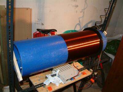
Larger diameters mean more inductance, which is good. But too much diameter causes trouble with field control, an immense toroid would be needed to shield the top turns of the secondary. Also, too much diameter might cause reduced coupling into the small single turn primary. Anyway, from the beginning I had decided to use 10" diameter pipe because it "looked about right". So the only thing to do was calculate wire gauge and toroid size to get the right resonant frequency. It has to be right first time because the tuning range of the primary is pretty small.
Toroid size was chosen for me, since there was a UK bulk buy of 8" x 24"s happening. That just left the wire gauge. I used the well known FANTC program which can simulate all aspects of the Tesla resonator in gruesome detail, and after some experimentation, I found that a 10"x 30" coil of 0.4mm gauge wire looked good. Later I checked this against "TeslaSim" by Antonio de Queiroz, and the numbers agreed pretty well. The only trouble was with the breakout voltage. Earlier, I calculated the OLTC II would generate something like 600kV. The breakout voltage for a 8" x 24" toroid is... something like 600kV. This isn't really a problem, it can always be fitted with a breakout point.
Next on the shopping list was about a mile of enamelled copper wire. This is more than any of the usual UK electronics outlets like Maplin, RS, Rapid, etc. sell in one piece. I phoned a local motor rewinder, who told me to go to Nexans Hi-Wire, a place which I never even knew existed. Hi-Wire happily sold me a 5 kilogram spool of 0.4mm wire with high temperature enamel.
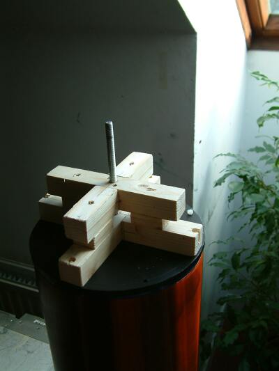
I also had to make end caps and a baffle to stop flashover between primary and secondary. To do this I picked up a large sheet of 10mm thick HDPE plastic. Chopping boards are usually a good source of HDPE, but they don't make them big enough for this job.
Tapping |
The bottom end cap in place |
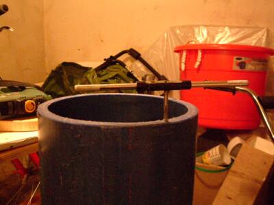
Having done this, the end caps were removed again. The baffle was cut to size and forced onto the pipe. Then the secondary was screwed onto a winding jig. This jig was made from several bits of Dexion angle iron screwed together and clamped in a Workmate.
A motor from an old cordless drill, geared with a bike chain and sprockets, spun the secondary while the wire was wound on. The motor was connected to a variable power supply so the speed could be controlled. If I was doing this kind of thing often, I would rig up a foot pedal for speed control, but it can still be done without one.
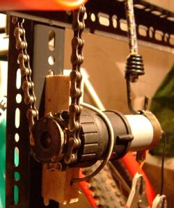
Motor with bike sprocket brazed to shaft |
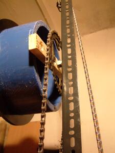
Bike chainring attached to secondary |
It actually took longer to make the jig than it did to wind the coil. The next step was to pour on some varnish as the coil was spinning, and leave it overnight (still spinning slowly) to dry.
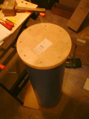
Unfortunately, as the varnish dried and everything settled, some of the turns began to stick out slightly above the rest. I have never managed to wind a "perfect" Tesla coil yet :-6 Anyway, once the varnish was dry, I installed the end caps (screwed and stuck on with silicone sealant) and made a holder for the toroid.