
Tesla Three
New control circuit
This new circuit does zero voltage turn-off. It waits until the collector voltage of the IGBTs goes negative (ie the flywheel diode is conducting) before turning off. This means that quenching at the wrong instant is now harmless. Before, there was a possibility of generating a kickback and popping the IGBTs. Now, the unused energy just gets dumped back into the tank capacitor. With this protection it is now possible to try for manually set first-notch quenching.
I also added a wide-range BPS control with a useful range from 2 to 1000bps.
The circuit below looks mighty complex. That's because I drew in the off-line power supply. In the previous version I just wrote "300V DC" with no mention of where it came from...
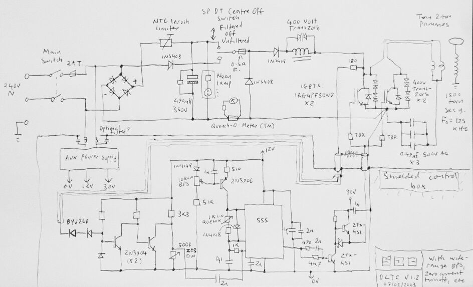
Version 1.2 schematic
Explanation
The ZVS/ZCS Circuit
The collector voltage of one IGBT is sensed. This is not straightforward because it can rise up to 700V but we are only interested in the small collector-emitter voltage (about 10vp-p) that appears when the switch is on. Two high-voltage fast-recovery diodes (BYV26D) are used to isolate the unwanted high-voltage portion of the collector waveform. Whenever the collector voltage goes negative, the diodes conduct and turn the transistor off, which turns the next transistor on. The output at this transistor's collector is a highly amplified square wave that goes negative whenever the collector voltage does. This is adjusted to size via a trimmer, differentiated, and fed into the 555's trigger pin.
The result is to give the trigger pin a little nudge every time the IGBT voltage goes negative. If it's just about to time out, then the nudge pushes it over the edge. Therefore, the ending of the gate drive pulse is locked to the nearest safe switching instant.
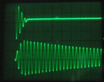
First notch quenching: 20us/div X, 50V/div Y. Top trace is tank cap voltage, bottom trace is pickup from antenna. Done at reduced HT voltage (50V)
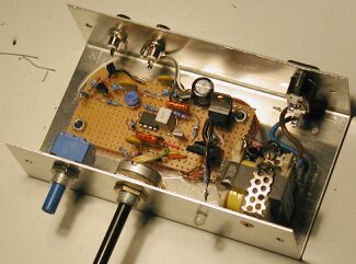
The new control circuit
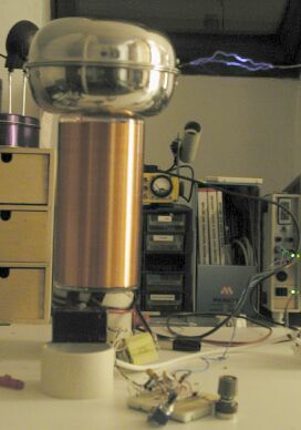
Running at about 5bps. Note new topload (required 0.188 uF of extra caps to tune)
The wide-range BPS control
Just putting a variable resistor into the standard 555 circuit doesn't give a very good control range. This circuit uses an adjustable current source instead. The firing rate can be controlled all the way from a Van de Graaff Generator-esque 2bps to a possibly suicidal 1,000bps. Transistor Q3 is a textbook current source, with the current set by the emitter resistor and the bias voltage applied to the base. Normally you see this with two diodes providing the base bias. I used one diode and a pot instead.
The power supply
This is fairly conventional. It's the same as you'll find in any switched-mode power supply and in fact you could just junk an old one to get the parts. The only difference is the option for unfiltered half-wave DC, which is an idea stolen from VTTC/SSTC builders.
The charging circuit
This is the same as a DC Tesla coil. The charging choke was taken out of an old tube amplifier. The only new things are the flywheel diode (which catches the kickback when you flip the high/low/off switch) and the transzorb across the choke (just in case)
Return to TC Page