
The primary circuit was hooked up to gate drivers, and power from a 0-300V supply via a DC resonant charging choke and diode.
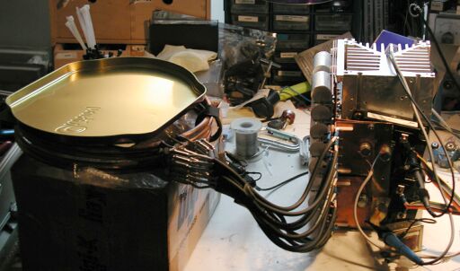
The above picture shows a biscuit tin lid used as a dummy load. It looks like a shorted turn, and the high resistance of the thin steel causes massive eddy current losses. First of all, though, some measurements were taken at reduced charging voltage (300V) with the lid removed, to see how lossy the actual primary was.
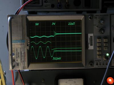
You can see that the losses are pretty small over the 3-cycle period. That's a good thing! Unfortunately it means the current is still pretty high at the quenching time, causing terrible reverse recovery transients from the diodes. We can't turn the voltage up any more or the ringing would get bad enough to breakdown the IGBTs :-0 So the biscuit tin has to go back in place to soak up some of that energy.
Next step was to bodge up a bigger power supply using a variac, isolating transformer, big caps wired in a voltage doubler, and an old MOT with the the "I" part of the core sawn off and the secondary removed.
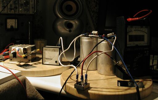
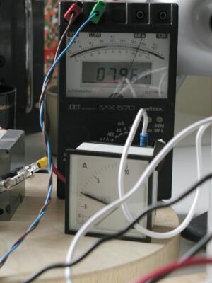
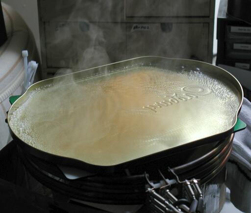
Using this power supply, I was able to feed 1.2kW in at 200bps. The tin lid got hot enough to boil water, and vibrated like crazy. I should mention how the charging voltage meter in the pic below works. It measures the voltage across a microwave oven cap which is connected in parallel with the tank cap, through its own de-Qing diode, so it gets charged to the same voltage as the tank cap, but doesn't discharge into the primary.
|
|