
The output from the MOT is about 2kV (RMS) AC. It feeds into a voltage multiplier (see voltage multiplier section below) that rectifies it into DC, smooths it, and also steps it up four times. It gives out 10kV DC at around 80mA.
Next are the de-Qing diode and charging reactor. These do more or less what the ballast does in a conventional AC coil. After the RSG fires, the tank cap recharges through the reactor. Because of the inductance, the tank cap ends up charged to twice the DC bus voltage (i.e. 20kV). The de-Qing diode (roughly speaking) stops the extra voltage draining back into the power supply. My design uses a 30 Henry charging reactor made from four off-the-shelf chokes in series. It can charge at up to 500bps.
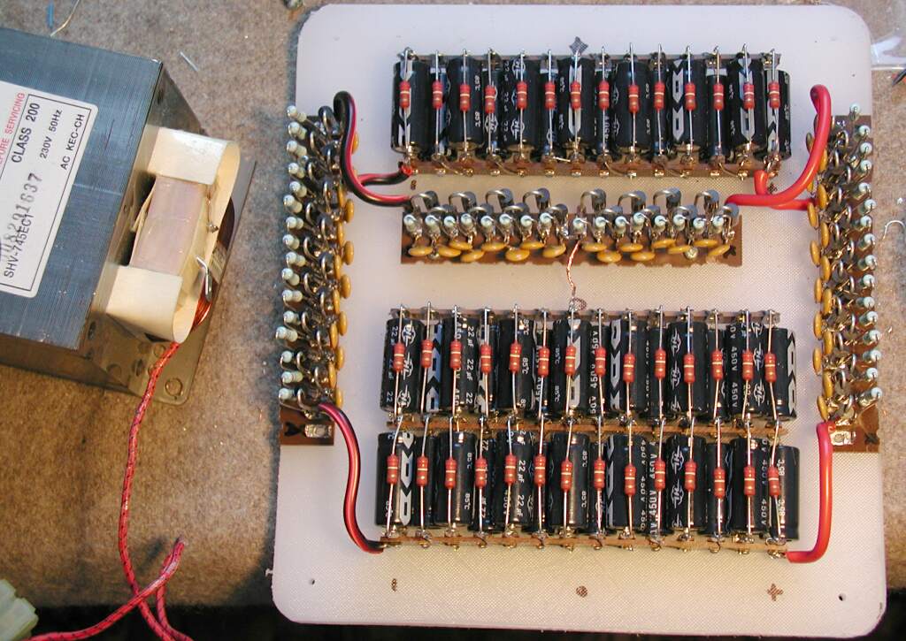
Voltage multiplier unit. MOT included for size comparison. Click image to enlarge
This is a very fancy version of the "level shifter" found in microwave oven applications. It's made from two voltage doublers stacked so it really gives + and - 5kV. This is safer, and gives more power than the regular Cockroft Walton circuit. Each diode is really 12 1N5408 diodes in series each with its own 1nF snubber cap and 1.2M equalising resistor. Each diode is rated 1kV so the string could ideally handle 12kV. It will never see more than 6kV in service so there is a 100% safety margin. (That's how generous you need to be with silicon.)
The caps are all made from series strings of 22uF 450V electrolytics each with a 220k bleeder resistor. In the 3uF positions I used 7 caps in series, in the 1.5uF positions 14 caps in series. That's a lot of caps but they are very small (and cheap)
I tested it first with 240V from a variac and isolating transformer. With 200V in it gave 1kV out. So I went ahead and hooked it to the MOT, with output unloaded. I wanted the voltage to go as high as possible, to test the insulation to the limit. I cranked the variac to 11 expecting it to blow to pieces, but it just buzzed a little. No ozone, corona or anything. I knew it was working because the bleeders were hot afterwards. It probably generated about 12kV.
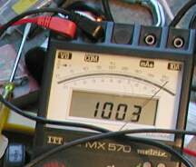
One thousand and three volts exactly
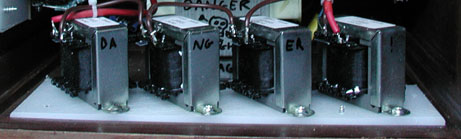
The four chokes installed in place