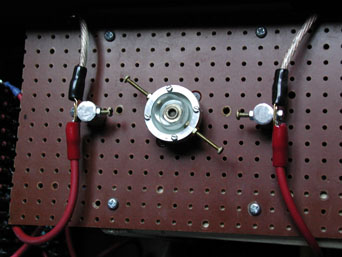


(Update 17 Feb 2003) Here is the completed rotary gap. The fixed electrodes are made from brass screws mounted in aluminium blocks. Everything is fitted on a piece of tough brown plastic of some sort (I believe it's phenolic or something) The two red leads supply DC from the charging circuit and the other leads go to the capacitor and primary coil. It works perfectly.

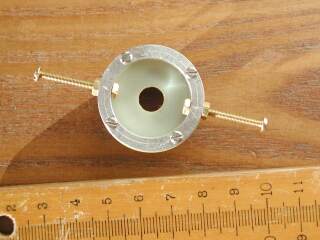
The rotor is made from an aluminium ring that I got out of an old hard drive. The scale is in centimetres. (small isn't it)

The ring is fixed to a fibreglass disk (piece of circuit board) using four tiny 2mm screws and nuts.

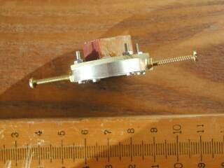
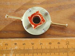
A block of phenolic plastic is epoxied to the back of the disk. The hole in the block was carefully filed so it fits the motor shaft perfectly with no play. The assembly was fitted to the motor with the glue still wet, centered so it spun perfectly true, and allowed to set.
The only worries are: The rotor might be too small, or it might arc from the ring to the motor shaft. The brass electrodes might work loose or snap. Heck, they might melt! P.S. They didn't.