Therefore, amp designers have tried to make transistorised amps that capture the sound of tube power. This is notoriously difficult to get right. Transistors just don't do the overdrive thing. So, there have been hybrid designs which try and combine a small tube preamp with a transistor power amp. These work all right, but in my opinion they miss one very important characteristic; the way in which the tube power stage interacts with the speaker load. The output impedance of a tube amp is higher than a solid-state one, and varies in a complex way with frequency and output level. If you run a hybrid design, or even a complete tube amp into a dummy load and then a line-out from this to a solid-state power amp, you lose this dimension.
So, for ages I racked my brains as to how to make it work. I wanted a way in which a small tube amp could be connected to a speaker, but with a massive transistor PA alongside it acting as a servo assist. The audio equivalent of power steering in your car. The steering wheel still connects physically to the roadwheels, so you can feel how they are interacting with the road. But there is a little hydraulic do-hickey that helps out by giving the steering rack a shove. I thought up all kinds of fancy and impractical circuits until one day the proverbial light bulb above the head went on...

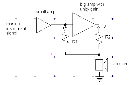
When the original tube amp (small amp in picture) drives the speaker, it delivers current I1. The big amp's input is hi-impedance so all the current goes through R1 to the speaker. This causes a voltage drop, let's call it V1, across R1. The big amp having unity gain, the voltage at its output is the same as its input, and so the voltage across R2 will be forced to be the same as that across R1. Therefore, from the big amp's output will come a current;
I2=V2/R2=V1/R1
and therefore
I2=I1*R1/R2
The current through the speaker will be I1+I2, in other words
Isp=I1(1+R1/R2)
So we have created a current assist that we can vary by changing the ratio R1/R2. By letting R1=R2, the current will be doubled. If R1=9R2, the current will be boosted by a factor of ten.
Of course, boosting the current is just one aspect of power boosting, we need to raise the voltage too. Put another way, as the current boost is cranked up, the load impedance seen by the small amp's output will increase.
Z=V/I
Now our current booster works according to Isp=I1(1+R1/R2) and hence I1=Isp/(1+R1/R2)
and hence the impedance seen by the small amp will be Z=Zsp(1+R1/R2) where Zsp is the speaker impedance. This proves that the tube amp still sees any dynamic impedance changes in the speaker, which was one of the things we wanted to achieve.
So, if we were to take a 4 ohm speaker, and apply the current boost with R1=3R2, the current would be increased by a factor of 4. The impedance seen by the small amp would then be 4(1+3)=16 ohms. So, if we were to take a 50 watt tube amp, we would drive the circuit using the 16 ohm output tap. The tube amp would contribute 50 watts and the big solid-state amp would contribute 150; the total power would be 200 watts into 4 ohms.
By a similar line of reasoning, the solid-state amp sees a load impedance of Z=Zsp(1+R2/R1) and so we would need an amp capable of delivering 150 watts into 4(1+1/3)=5.33 ohms.
Of course the theory is easy enough but building a unity-gain high-power amp is a bit more tricky. The more accurate the gain is, the smaller R1 and R2 can be made, and hence the less power will be wasted in heating them up. This is what is holding Project Boots up. Watch this space.