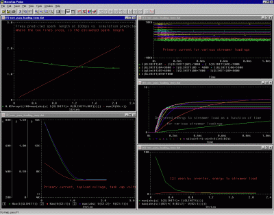
Screenshot from the parametric sim
http://www.pupman.com/
http://groups.yahoo.com/group/tcbouklist/
The most useful thing I have come up with so far is this PSpice simulation set for predicting DRSSTC behaviour. It uses the parametric and transient functions to simulate the coil 10 times with 10 different possible streamer lengths. There are preset displays in Probe (and a .cmd file to bring them up) that show all the parameters.

A second version of the simulation set uses primary inductance as the parameter so you can easily find the tuning point for your coil. This seems to suggest that tuning the primary too low gives a safety margin.
These sims model self-resonant coils. They resonate at whatever pole has the highest gain, and can even hop between poles mid-burst like a real coil might. However you can easily modify the sim to model an oscillator-driven coil.
They also use a "hungry streamer" model where the streamer resistance adjusts itself to be equal to the capacitive reactance (which is set to be a function of the length. This seemed to give more believable results than Terry's 220k + (1pF/foot) rule of thumb. I could reproduce the bizarre ringup behaviour of the Tesla-6 using the hungry streamer model but not the Terry one. I've yet to retry with the new impedance figures from the OLTC II tests.
Download PSpice files:
drsstc_sim.zip
An older non-parametric version of the sim:
fbdrsstc.sch
fbdrsstcip.sch
fbdrsstciparc.sch
Speaking of which, there is still some controversy over the best way to design a DRSSTC. I favour the self-resonant type where the coil operates at a frequency roughly equal to the lower peak of the unloaded response. This is the design that Steve Ward and Dan Mc. use.
However Antonio de Queiroz (who is a well respected expert on Tesla transformer theory) favours a design that is driven midway between the two peaks. This causes a "beat" effect that is claimed to give more efficient energy transfer to the secondary. I have simulated Antonio's designs and my results agree with his, as long as I make the same loading assumptions he does. (namely that the coil is unloaded until almost the end of the energy transfer)
But I'm not convinced that this is actually true in practice. The DRSSTC trend is to try and produce the most impressive streamers compared to the resonator size. This means that the streamer loading starts early (small toroid/breakout point) and is heavy. I think that "Antonio Mode" loses its advantage under these conditions. It may be more efficient in theory, provided the coil is designed for it. But it needs a larger resonator, as the resonator has to accept all the bang energy before breaking out.
In "Ward Mode" I believe the resonator can be about sqrt(k) times smaller without flashing over, as it only contains k times the bang energy at breakout and the other (1-k) is delivered straight into the discharge.
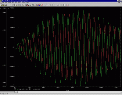
For instance I've been looking at a coil with k=0.2. If the primary is tuned almost exactly to the secondary, then the primary current shows an envelope with notches as Antonio's tunings do- even with a self-resonant driver running off primary current feedback.

The voltage is not high enough for breakout till the second notch, but once it has broken out it seems to maintain a healthy primary current (300A with the components I chose) and continue delivering energy. In the picture above I simulated breakout at 50us and ended the drive at 100us. About 6 joules were delivered, even though the secondary capacitance can only store 0.9 at breakout.
This behaviour seems to be stable over a wide range of simulated streamer lengths. The peak primary current seems to decrease as the streamer loading gets heavier, although if it got really heavy it would probably go up again.
It also works nearly as well if the primary is tuned slightly low. In the simulation shown above I used about 10% more inductance than the "exact" value where L1*C1=L2*C2.
Parameters of the coil I simulated-
Primary inductance 21uH
Primary cap 52nF 9kV
Secondary inductance 43mH
Secondary capacitance including 4" x 16" toroid 20.5pF
Resonant frequency 171kHz
Characteristic impedance 46kOhm
Coupling 0.2
DC link voltage 377V (full bridge)
Primary current limit 400A