Unfortunately this is a bit more complex than the last one. There are two adjustable time delays. During the first one, the IGBTs must stay on. The end of this delay should be set slightly before the desired quenching point. When it expires, the second delay is started, and the Rogowski coil is enabled. This samples the primary current, and as soon as the Rogowski coil sees the primary current passing through zero in a negative direction, the IGBTs are turned off.
Of course there is a flaw in this scheme. If for some reason the Rogowski coil doesn't trip (maybe the DC link voltage is very low, so the primary current is too weak to trigger it) the IGBTs will stay on for ever! This would mean that the system could never start up. That's what the second time delay is for: It turns the IGBTs off in the event that the Rogowski coil didn't. This delay should be set long enough to let the primary current decay to a safe value. In practice the Rogowski coil kicks in at a DC link voltage of around 50-100V, depending on how heavily the primary is loaded.
This circuit reduces the probability of toasting the IGBTs. To reduce it still further, a crowbar circuit is provided. This monitors the voltage across the R-C-D snubber circuit, which is the same as the IGBT peak collector voltage. When this exceeds a threshold (set by a trimmer) the IGBTs are turned on continuously and the power must be cycled to reset them.
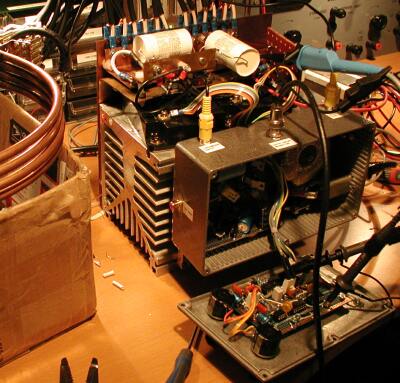
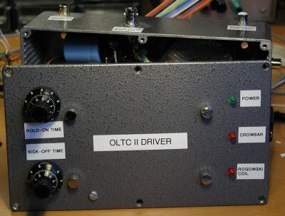
The new driver circuit was placed in a RF-proof aluminium case, along with the 240V:15-0-15V transformer that powers it, and a filtered IEC inlet. Signal connections are made via RCA sockets. The trigger pulses will be transmitted through a shielded cable and then sent into the box through a pulse transformer, which will be outside the box to minimise capacitively coupled interference. If that doesn't work, I'll have to use fibre optics.