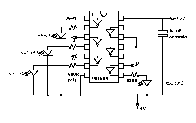
The MIDI lines all pulse 'low' when they are active. The 74HC04 is an inverter, so its outputs will go 'high'. Therefore, you connect the LEDs between the outputs and ground. Since the 04's outputs are only rated at a few mA, you need to use high-efficiency (aka high-brightness) LEDs. Resistors are used to restrict the current to 5mA.
The arrows in the circuit indicate connections to the EWS front panel PCB. Connect wires to your stripboard at these points. Use thin wires, because you will be soldering them to tiny surface-mount components. Also, you will probably have to put the LEDs on flying leads, for instance if you want one above each MIDI socket.
P.S. The IC is static sensitive.
I didn't want to just change the picture, in case it caused confusion. Sorry.

Have a tea break. Then double-check your work against the circuit diagram. Look for solder bridges, chips in upside-down, etc.
Connect wires A,B,C, and D to the +5V wire, via one 4.7K resistor each. Then connect the 5V and 0V wires to a power supply. Measure the current draw with the multimeter. No LEDs should light, and the current draw should be only a few hundred microamps. If it is more than this, switch off quickly and check your work.
Now test the LEDs one at a time. Remove one of wires A,B,C or D (why not try A :) ) from the 5V supply, along with its resistor. Connect it to 0V, again via the resistor. Check that the corresponding LED lights up. Reconnect the wire and resistor to 5V, and try another one.
Unplug the front panel, take it out of the computer, undo the screw in the middle of the front panel PCB, and lift it out of the silver chassis. Careful, the circuit board is static sensitive.
Solder the wires from your stripboard to these points on the front panel PCB. Use a fine soldering iron, and be careful with B and D; too much heat can make the SMT components fall off the board.

For goodness' sake don't get them mixed up! You could toast your EWS (see Disclaimer)
Now use a centre punch to mark where you want each LED. This stops the drill bit skidding. Clamp the chassis securely and drill the holes.
Secure the stripboard to the front panel PCB, using double-sided sticky pads. If you have a daughterboard fitted, it might be a bit of a squeeze. Replace the PCB in the front panel chassis, and stick the LEDS through their holes. Fix them in with epoxy glue, or use special panel mounting kits (if you're posh)
Modifying the EWS for balanced ins/outs and reduced noise (hardcore hackers only)