
If you have read the rest of this series, you may have noticed that the Tesla-4 includes a crowbar circuit. This senses the voltage across the main IGBTs, and if it reaches a dangerous value, turns the IGBTs on permanently. This is the right way to get rid of an overvoltage, but it shorts out the main power supply, which is bad.
The main power supply has a 20A circuit breaker which would protect most of the components, but not all of them. Consider what happens when the DC link is shorted. The filter capacitors will dump into the charging reactor, ramping the current up. The current will reach a peak of around 100A, possibly burning out the de-Qing diode which is only rated for 30A. If the thyristors are still firing, current from the mains will make things even worse. But if the thyristor drive is cut off in an attempt to limit the overcurrent, things will go wrong in a more subtle way.
The charging choke current will reach a peak as the filter cap voltage reaches zero. But there is still a lot of magnetic energy stored in the choke, and this will keep the current flowing and drive the filter cap voltage negative. Electrolytic caps won't like that.
So how do we protect against these calamities? A circuit breaker in the DC link would be ideal. But unfortunately, ordinary AC circuit breakers may not quench a DC arc. This circuit is especially bad because there is a high voltage and plenty of inductance, so I think the breaker would probably go to a fiery grave 8-0
In the end, I chose a double approach. I made a circuit that detects overcurrent and interrupts the DC link with an IGBT. At the same time it shuts down the thyristor drive, so basically the whole power supply goes to a safe condition. Here is the circuit. It's pretty simple and may have applications in other areas.

*SAFETY WARNING*
As you may have noticed, the "ground" rail of this little circuit is connected to the HV output. Therefore the whole circuit will float at a high voltage when in use. This is why it is powered by its own little transformer, and the interlock signal goes through an optoisolator. You will have to take special care when trying to measure voltages on the circuit while it is in use.
The circuit is based around a flip-flop made from Q1 and Q2. R4 unbalances it slightly to make sure it always goes into the proper state when power is applied. In this state, Q1 is on, Q2 is off, so voltage is applied to the IGBT gate, and the breaker is "on". Q1 also turns the optoisolator on, telling the thyristor driver board that everything is all right over in DC link land.
This happy carefree state persists until the DC link current gets high enough to develop about 0.65V across R7. (In this case about 13A.) This makes Q3 conduct, which drains base current away from Q1 and causes it to turn off. This causes the flip-flop to flip to the other state, with Q1 off and Q2 on. In this state, the IGBT is turned off, breaking the DC link circuit. D2 catches the current flowing in the charging reactor allowing it to decay safely. The optoisolator also turns off, causing the thyristor driver to shut down immediately. To reset the circuit, the power must be turned off for a few seconds and then back on again.
This circuit interrupts the DC link current very quickly, far faster than a mechanical circuit breaker. This can lead to a voltage spike caused by stray inductances, which could damage the IGBT. C4 is included to try and damp this spike down. Keeping the wires between the circuit inputs and the main filter caps short and close together will also help by minimising stray inductance. The output wiring doesn't matter, since it includes the charging reactor which is a very large "stray" inductance indeed...
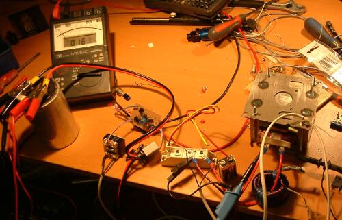
A prototype of this circuit was built and tested. The input was hooked up to a 1200uF 400V capacitor that could be charged from a power supply. The output was hooked up to a large thyristor via the same charging reactor that would be used in the finished PSU. The thyristor could be fired by pressing a button on the end of a few feet of wire. This would cause a short circuit just the same as the crowbar in the finished system, and also trigger a scope so I could see what happened.
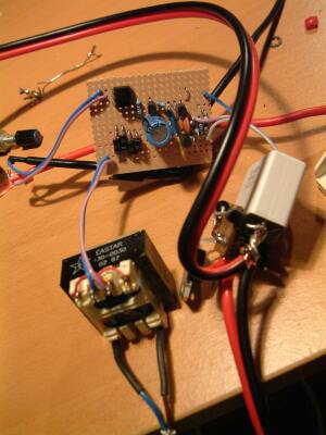
Prototype |
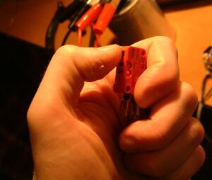
Everybody get behind the sofa!!! |
The first attempts were a bit of a laugh. The circuit triggered OK, but then it went totally unstable, flipping and flopping around at high frequency. But after a few mods (I added C3, C2 and R8) I had it doing what I wanted.
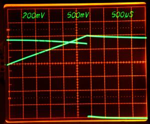
In this screenshot you can see how it works. The upper trace is the DC link voltage (50V/div) and the lower trace is the current measured with a current transformer (not cal'd) The trace starts at the instant the thyristor is fired. The current begins to ramp up, the DC link voltage falling as the cap discharges. But after 5 and a bit divisions, the breaker trips. The DC link voltage suddenly falls to zero, and the current starts to fall.
This shot was taken with a 2 second exposure. The scope was in single sweep mode, triggered by the thyristor anode voltage.