System diagram
Here you can see how the little circuits I have described hook together to form the finished OLTC II. Some small parts are not shown, such as the power supplies for the trigger generator, and IGBT driver.
"It was a dark and dreary night in January, when I first beheld the accomplishment of my coil."
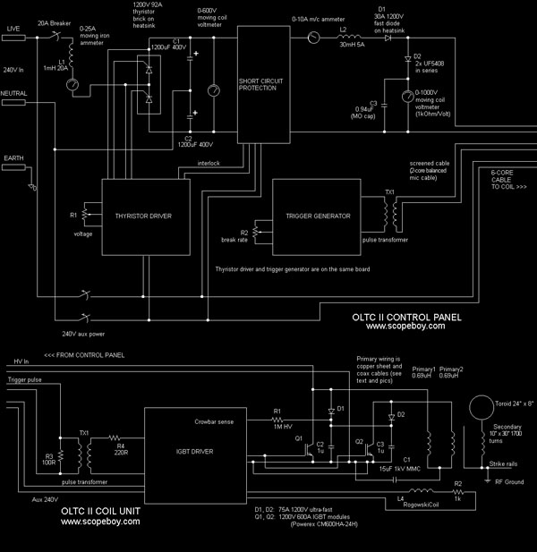
System block diagram. Click image for larger printable version
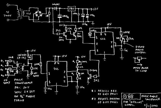
Thyristor driver
Trigger generator
Note: The trigger generator runs off the thyristor driver's 12V rail.
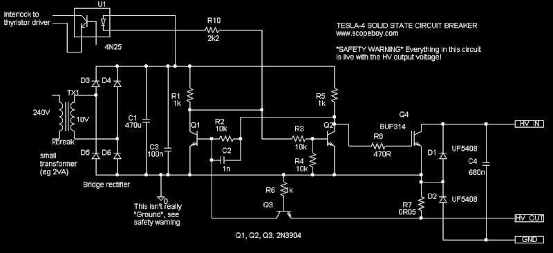
Short circuit protection, click to enlarge
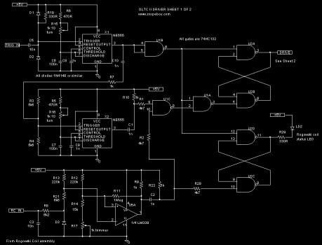
IGBT driver sheet 1/2 (click to enlarge)
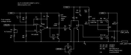
IGBT driver sheet 2/2 (click to enlarge)
Note: The IGBT driver power supply is not shown. It uses a 15-0-15V transformer with rectifier, filter caps, 7812 and 7805 regulators for the +12 and +5 rails, and a LM317 giving an adjustable 20 to 30V rail.
<<< Previous: Short circuit protection
Next: The end is in sight >>>
Return to TC Page